Table of Contents
Advertisement
Quick Links
Advertisement
Table of Contents

Related Manuals for Spectrex SHARPEYE 20


Summary of Contents for Spectrex SHARPEYE 20
- Page 1 Model 20/20MI Mini Triple IR (IR3) Flame Detector User Guide Document ref: TM 787100, Rev. (Af), May 2019 8200 Market Blvd, Chanhassen, MN 55317, USA Phone: +1 (973) 239 8398 Fax: +1 (973) 239 7614 Website: www.spectrex.net; Email: spectrex@spectrex.net...
-
Page 3: Legal Notice
Legal Notice The SPECTREX SharpEye Optical Flame Detector described in this document is the property of Rosemount. No part of the hardware, software or documentation may be reproduced, transmitted, transcribed, stored in a retrieval system, or translated into any language or computer language, in any form or by any means, without prior written permission of Rosemount. -
Page 4: Release History
Release History Prepared by Approved Date Revision History May 2017 Sixth Release Jay Cooley Shaul Serero May 2019 Seventh Release Michal Heller Udi Tzuri... -
Page 5: Table Of Contents
Table of Contents Model 20/20MI Mini Triple IR (IR3) Flame Detector ........i Legal Notice ....................iii Release History ....................iv About this Guide ..................... xi Abbreviations and Acronyms ................xii Scope ...................... 13 Product Overview ................. 13 Technical Description ................15 Features ..................... - Page 6 4.3.5 Addresses Setup ................31 4.3.6 Detector Default Setup ..............31 Built-In-Test ..................32 4.4.1 General ..................32 4.4.2 Principles ..................32 4.4.3 Automatic & Manual BIT ..............32 4.4.4 Manual BIT only ................33 Technical Specifications ................. 35 Electrical Specifications ................. 35 Mechanical Specifications ..............
- Page 7 8.3.1 Power-Up Procedure ..............51 8.3.2 Functional Test Procedure .............. 51 Maintenance Records ................52 Troubleshooting ................... 52 8.5.1 Fault Indication ................52 8.5.2 False Alarm or Warning Indication ........... 52 8.5.3 RS-485 Communications Network ........... 52 Appendix A Typical Wiring Configurations ..........53 Appendix B IR3 Flame Simulator FS-1100 ..........
- Page 8 List of Figures Figure 1: Types and Models ................17 Figure 2: Flame Detector Assembly - Outline Drawing (Cable Output Option) .... 18 Figure 3: Flame Detector Assembly - Outline Drawing (Connector Output Option) ..19 Figure 4: Horizontal and Vertical Fields of View ............. 23 Figure 5: Indication LEDs ...................
- Page 9 List of Tables Table 1: Alarm Response Time versus Range – 20/20MI-1 ........21 Table 2: Alarm Response Time versus Range – 20/20MI-3 ........21 Table 3: Response Sensitivity Ranges ..............22 Table 4: Sensitivity to Other Fire Sizes ..............22 Table 5: Immunity to False Alarm Sources ............
-
Page 11: About This Guide
About this Guide This guide describes the SharpEye Model 20/20MI Mini Triple IR (IR3) Flame detector and its features, and provides instructions on how to install, operate, and maintain the detector. This guide includes the following chapters and appendices: • Chapter 1, Introduction, provides a general introduction and overview of the product. -
Page 12: Abbreviations And Acronyms
Abbreviations and Acronyms Abbreviation Meaning American Wire Gauge Built-In-Test Electromagnetic Compatibility End of Line Field of View Immune at Any Distance Isopropyl Alcohol Infrared Jet Fuel Latched Refers to relays remaining in the On state even after the On condition has been removed Light Emitting Diode Liquefied Petroleum Gas Milliamps (0.001 amps) -
Page 13: Scope
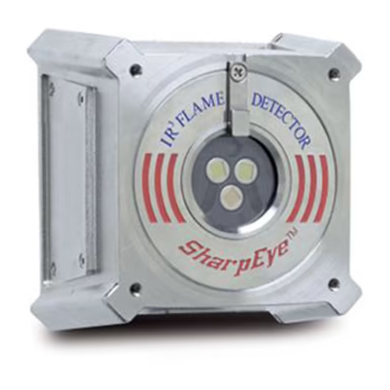
Product Overview Scope Product Overview The SPECTREX Model 20/20MI is a new version of the triple IR spectrum flame detector designed to provide maximum fire protection. It uses innovative technology of advanced digital signal processing to analyze the dynamic characteristics of fire. Three sensitive IR channels process the signals. -
Page 15: Technical Description
Principles of Operation Technical Description Features The SharpEye Model 20/20MI Mini Triple IR (IR3) Flame Detector includes the following features: • Detection Range: up to 132ft/40m for a 1ft /0.1m fire • Ultra High Immunity to False Alarms (see False Alarms Detection, page 24) •... -
Page 16: Limitations Of Ir-Ir Flame Detectors
Their immunity to false alarm sources is limited. 2.2.4 Advantages of IR3 Technology To overcome these limitations, SPECTREX devised an innovative concept of utilizing an additional detection channel. Three channels collect more data from the environment, providing a more accurate analysis and better performance. -
Page 17: Types And Models
Principles of Operation 2.2.6 Types and Models The 20/20MI has 2 models: • Standard - up to 40m • Short range - up to 10m Optional: The output is via either a connector or a cable tail (up to 2m long). Figure 1: Types and Models F- FM and EN54-10 –... -
Page 18: Figure 2: Flame Detector Assembly - Outline Drawing (Cable Output Option)
Principles of Operation Figure 2: Flame Detector Assembly - Outline Drawing (Cable Output Option) SharpEye IR3 Flame Detector User Guide... -
Page 19: Figure 3: Flame Detector Assembly - Outline Drawing (Connector Output Option)
Principles of Operation Figure 3: Flame Detector Assembly - Outline Drawing (Connector Output Option) TM 787100 Rev (Af), May 2019... -
Page 21: Performance
Detection Sensitivity Performance Detection Sensitivity Detection sensitivity is the maximum distance at which the detector will reliably detect a specific size of fire and typical type of fuel (standard fire). 3.1.1 Standard Fire A standard fire is defined as a 1ft /0.1m gasoline pan fire with maximum wind speed of 6.5ft/sec / 2m/sec. -
Page 22: Other Fuels
Detection Sensitivity 3.1.3 Other Fuels The detector reacts to other types of fires as shown in Table 3: Table 3: Response Sensitivity Ranges Type of Fuel % of Max. Distance at Each Sensitivity Range Gasoline 100% N-Heptane 100% Alcohol 95% Kerosene Diesel Fuel Methane*... -
Page 23: Cone Of Vision
Cone of Vision Cone of Vision • Horizontal: 100° • Vertical: 100° Figure 4: Horizontal and Vertical Fields of View TM 787100 Rev (Af), May 2019... -
Page 24: False Alarms Detection
False Alarms Detection False Alarms Detection The detector does not provide an alarm or a warning signal as a reaction to the radiation sources specified in Table 5. Table 5: Immunity to False Alarm Sources Radiation Source Immunity Distance ft/m Sunlight Indirect or reflected sunlight Incandescent frosted glass light, 100 W... -
Page 25: Table 6: Welding Immunity Distance - 20/20Mi-1
False Alarms Detection Table 6: Welding Immunity Distance – 20/20MI-1 Sensitivity Detection Range Immunity Distance (ft/m) (ft/m) 33/10 >10/3 65/20 >15/5 100/30 >20/7 132/40 >33/10 Table 7: Welding Immunity Distance – 20/20MI-3 Sensitivity Detection Range Immunity Distance (ft/m) (ft/m) 8.2/2.5 >2.5/0.75 16.5/5 >5/1.5... -
Page 27: Operation
Visual Indications Operation Visual Indications One 3-color LED-indication is located in the detector front window: Figure 5: Indication LEDs TM 787100 Rev (Af), May 2019... -
Page 28: Output Signals
Output Signals The LEDs are described in Table 8. Table 8: 20/20MI Status Detector LED color LED mode Status Fault, BIT Fault Yellow 4 Hz flashing Normal Green 1 Hz flashing Warning 2 Hz flashing Alarm Steady Output Signals The detector controls the following outputs: •... -
Page 29: Optional Latching
Refer to Detector Default Setup on page 31 for default factory settings. The detector incorporates several functions that can be set by the customer using SPECTREX host software, which is supplied with each detector shipment. Please refer to Manual TM768050 for programming instructions. -
Page 30: Sensitivity Ranges
Detector Mode Setup 4.3.2 Sensitivity Ranges The detector offers 4 sensitivity settings. The settings refer to the gasoline fire of 1ft from 33ft/10m to 132ft/40m for Model 20/20MI-1 and 8.2ft/2.5m to 33ft/10m for Model 20/20MI-3. For other types of fuel sensitivity, refer to Table 11. Table 11: Sensitivity ranges Sensitivity 20/20MI-1... -
Page 31: Function Setup
Detector Mode Setup Table 12: Time Delay Delay (seconds) A (anti-flare) 3 (default) Note: The FM approval does not allow use of 20 and 30 second setting delay. 4.3.4 Function Setup You can select the desired mode of operation by means of the host. Table 13: Function Setup Name Alarm Latch... -
Page 32: Built-In-Test
Built-In-Test Table 14: Default Function Setup Detector Default 20/20MI-1 20/20MI-3 Setup: Sensitivity Delay Alarm Latch Automatic BIT Alarm BIT Built-In-Test 4.4.1 General The detector’s Built In Test (BIT) checks the following: • Electronics circuitry • Sensors • Window cleanliness The detector can be set to perform the BIT as: •... -
Page 33: Manual Bit Only
Built-In-Test 4.4.3.2 Automatic BIT The detector automatically performs a BIT every 15 minutes. A successful BIT does not activate any indicator. • The fault relay remains closed (normal). • The LED continues to flash (1Hz) at green. • The 4–20mA output continues to indicate 5mA. An unsuccessful BIT sequence activates the following: •... -
Page 35: Technical Specifications
Electrical Specifications Technical Specifications Electrical Specifications • Operating Voltage: 18–32VDC • Power Consumption: Max. 25mA in standby Max. 50mA in alarm • Electric Input Protection: • The input circuit is protected against voltage-reversed polarity, voltage transients, surges, and spikes according to MIL-STD-1275A. -
Page 36: Mechanical Specifications
It enables continuous communication between a single-standard Modbus controller (master device) and a serial network of up to 247 detectors. • It enables connection between different types of SPECTREX detectors or other Modbus devices to the same network. Mechanical Specifications •... -
Page 37: Environmental Specifications
Environmental Specifications Environmental Specifications • High Temperature Designed to meet MIL-STD-810C, method 501.1 procedure II • Operating temperature: +160°F / +70°C • Storage temperature: +185°F / +85°C • Low Temperature Designed to meet MIL-STD-810C, method 502.1, procedure I –40°F / –40°C •... - Page 38 Environmental Specifications Electromagnetic Compatibility (EMC) This product is in conformance with EMC directive 89/336/EC. • Radiated Emission EN61000-6-3 • Conducted Emission EN61000-6-3 • Radiated Immunity EN61000-4-3 • Conducted Immunity EN61000-4-6 • EN61000-4-2 • Burst EN61000-4-4 • Surge EN61000-4-5 SharpEye IR3 Flame Detector User Guide...
-
Page 39: Installation Instructions
General Considerations Installation Instructions Scope The SharpEye Model 20/20MI is a self-contained optical flame detector designed to operate as a stand-alone unit directly connected to alarm systems or automatic fire extinguishing systems. The detector can be a part of a more complex system where many detectors and other devices are integrated through a common control unit. -
Page 40: Preparations For Installation
Conduit Installation • Environment • Dust, snow, or rain can reduce the detectors sensitivity and require more maintenance activities. • The presence of high intensity flickering of IR sources may affect sensitivity. Preparations for Installation Installation should comply with NFPA 72E or local regulations, as applicable to flame detectors. -
Page 41: Tilt Installation
Conduit Installation 6.4.2 Tilt installation Refer to Figure 6 and Figure 7. Place the tilt mount (Item 1) in its designated location and secure it with 3 fasteners through 3 holes 5.2mm in diameter (Figure 7). Note: Skip this step if the tilt mount is already installed. Also, detector removal for maintenance purposes does not require tilt mount removal. -
Page 42: Figure 6: Ir3 Detector And Tilt Mount Assembly
Conduit Installation Description Tilt Mount Holding Screws Detector Holding Plate Washers Mounting Plate IR3 Detector Direct Mounting Holes Locking Screw Figure 6: IR3 Detector and Tilt Mount Assembly SharpEye IR3 Flame Detector User Guide... -
Page 43: Figure 7: Tilt Mount Assembly - Outline Drawing
Conduit Installation Description Tilt Mount Mounting Plate Detector Holding Plate Locking Screw Figure 7: Tilt Mount Assembly - Outline Drawing TM 787100 Rev (Af), May 2019... -
Page 44: Detector Installation
Wiring Function Detector Installation In order to comply with intrinsically safe requirements when the detector is used in hazardous areas, barriers must be incorporated. There will also be restrictions on cable types and lengths, depending on the type of barriers used. -
Page 45: Operation Mode
Alarm Latch Automatic BIT Alarm BIT You can reprogram the function setup through RS-485 using a PC with a SPECTREX host, or using a handheld unit. Refer to Manual TM 768050 for instructions. 6.7.1 Programmable Function Modes of operation are programmable with a PC or handheld unit according to the selection table in Sensitivity Ranges on page 30. -
Page 46: Alarm Delay
Operation Mode 6.7.3 Alarm Delay An alarm delay may be required for certain applications. The detector has an alarm delay that permits time delays from 0, anti-flare, 3, 5, 10, 15, 20, and 30 seconds respectively. The delay can be defined by the RS-485. Refer to Manual TM 768050 for further instructions. -
Page 47: Operating Instructions
Power Up Operating Instructions This chapter describes how to power up and test the detector. It also includes some very important safety checks that you should make before operating the detector. Scope The following instructions are designed to obtain optimal performance from the detector over its life cycle. -
Page 48: Reset
To reset a detector when in it is in alarm state, disconnect the power. Functional Testing The detector can be tested for proper functioning using the Manual Built-in- Test or the SPECTREX IR3 Flame Simulator - FS-1100. 7.4.1 Manual BIT Test Momentarily connecting PIN number 11 (yellow wire) with PIN 2 (black wire) causes a manual BIT to be performed. - Page 49 The 1Hz LED flashes green. Aim the SPECTREX Flame Simulator Model FS-1100 at the target point of the detector (see Figure 16: Flame Simulator), in such a way that the radiation emitted by it is facing directly towards the detector. (See IR3 Flame Simulator FS-1100 on page 57) Press the operation button once.
-
Page 50: Safety Precautions
• Do not touch internal parts other than the 3 functional switches. Interference with internal circuits may impair detector performance and will invalidate the SPECTREX warranty. • Disconnect external devices, such as automatic extinguishing systems, before carrying out any maintenance. -
Page 51: Maintenance Instructions
Periodic Maintenance Procedures Maintenance Instructions This section deals with preventive maintenance, describes possible faults in detector operation and indicates corrective measures. Ignoring these instructions may cause problems with the detector and may invalidate the warranty. Whenever a unit requires service, please contact the manufacturer or its authorized distributor for assistance. -
Page 52: Maintenance Records
• Entries for every maintenance operation performed, including the description of the operation, date, and personnel ID. If a unit is sent to SPECTREX or a distributor for service, a copy of the maintenance records should accompany it. Troubleshooting 8.5.1... -
Page 53: Appendix A Typical Wiring Configurations
Typical Wiring Configurations Appendix A Typical Wiring Configurations Figure 10: Connector Interface Option TM 787100 Rev (Af), May 2019... -
Page 54: Figure 11: Cable Interface Option
Typical Wiring Configurations Figure 11: Cable Interface Option Figure 12: RS-485 Networking SharpEye IR3 Flame Detector User Guide... -
Page 55: Figure 13: 4-20Ma Wiring (Sink Option)
Typical Wiring Configurations Figure 13: 4–20mA Wiring (Sink Option) Figure 14: 4–20mA Wiring (Source Option) Notes: The detectors are factory set to isolated 4–20mA-sink versions. To work at a non-isolated 4–20mA source version, connect PIN 3 or the blue wire to PIN 1 or the red wire. This can be done on the mating connector or in the junction box in the cable option. -
Page 56: Figure 15: Typical Wiring For 4 Wire Controllers
Typical Wiring Configurations Figure 15: Typical Wiring for 4 Wire Controllers Notes: • For EOL resistor value see the Controller Manual. • The color wire refers to the color of the cable output option. The PIN No. refers to the connector option. SharpEye IR3 Flame Detector User Guide... -
Page 57: Appendix Bir3 Flame Simulator Fs-1100
IR3 Flame Simulator FS-1100 Appendix B IR3 Flame Simulator FS-1100 Description The Flame Simulator FS-1100 is designed specifically for use with SharpEye Flame Detectors. The flame simulator emits IR radiation in a unique sequential pattern corresponding to and recognizable by the detector as fire, which allows the detectors to be tested under simulated fire conditions without the associated risks of an open flame. -
Page 58: Operation
Operation Operation Figure 17: Mini IR3 Detector Target Point Warning: Do not open the flame simulator to charge the batteries or for any other reason in a hazardous area. Caution: The following test will simulate a real fire condition and may activate the extinguishing system or other alarms. -
Page 59: Charging The Battery
Charging the Battery Charging the Battery The flame simulator uses NiCad batteries as a rechargeable power source. When the batteries are fully charged, the simulator operates at least 60 times without recharging. An internal buzzer is sounded when the voltage from the batteries is lower than the required operational level. -
Page 61: Appendix Cfm Report For 20/20Mi-3
FM Report for 20/20MI-3 Appendix C FM Report for 20/20MI-3 Examination and Test Four samples of Model 20/20MI-3 Flame Detector, representative of production units, were examined and tested at FM Approvals in Norwood, Massachusetts. One sample was examined, tested, and compared to the manufacturer’s drawings. - Page 62 FM Report for 20/20MI-3 Detector Fuel Distance to Sensitivity Response Model Fire (ft/m) setting (seconds – average) 20/20MI-3 n-heptane 33/10 20/20MI-3 n-heptane 24.7/7.5 20/20MI-3 n-heptane 16.5/5 20/20MI-3 n-heptane 8.2/2.5 20/20MI-3 Diesel 23.1/7 20/20MI-3 Diesel 17.3/5.3 20/20MI-3 Diesel 11.5/3.5 20/20MI-3 Diesel 5.7/1.7 20/20MI-3 Ethyl Alcohol...
- Page 63 FM Report for 20/20MI-3 Field of View Test One sample of the Model 20/20MI-1, which has an identical enclosure to the 20/20MI-3 and is considered representative of the series, was exposed to the 12 x 12” / 0.3 x 0.3m n-heptane pan fire during which time the viewing angle was varied +/–50º...
-
Page 68: Technical Support
Technical Support For technical assistance and support, contact: 8200 Market Blvd Chanhassen, MN 55317 Phone: +1 (973) 239 8398 Fax: +1 (973) 239 7614 Email: spectrex@spectrex.net Website: www.spectrex.net...
Need help?
Do you have a question about the SHARPEYE 20 and is the answer not in the manual?
Questions and answers