Allied Telesis AR Series Hardware Reference Manual
Hide thumbs
Also See for AR Series:
- Configuration (43 pages) ,
- Technical manual (75 pages) ,
- Hardware reference manual (100 pages)
Table of Contents
Advertisement
Advertisement
Table of Contents

Related Manuals for Allied Telesis AR Series


Summary of Contents for Allied Telesis AR Series
- Page 1 AR SERIES ROUTER HARDWARE REFERENCE...
- Page 2 AR Router AR Router Hardware Reference Document Number C613-03031-01 REV E. Copyright © 1999-2002 Allied Telesyn International, Corp. 19800 North Creek Parkway, Suite 200, Bothell, WA 98011, USA. All rights reserved. No part of this publication may be reproduced without prior written permission from Allied Telesyn.
-
Page 3: Table Of Contents
Hardware Reference Contents Introduction ...................... 4 Models Covered By This Reference ..............5 Where To Find More Information ..............5 Using Windows Terminal and Windows Hyperterminal ........6 Router Start-up ....................9 Online Documentation ..................14 To Access Online Documentation .............. 14 AT-TFTP Server .................... - Page 4 AR Router Installing a MAC ..................94 Installing a PAC ..................98 Installing a Flash SIMM ................104 AT-AR720 Dip Switch Settings ..............105 Diagnostics ..................... 106 Replacing Boot EPROMs ................. 108 Contacting Us ....................111 C613-03031-01 REV E...
-
Page 5: Introduction
Hardware Reference Introduction This Hardware Reference describes the hardware features of all AR300, AR400, and AR700 Series router models, including information on Mini Accelerator Cards (MACs) and PCI Accelerator Cards (PACs). Hardware and installation information for Port Interface Cards (PICs) and Network Service Modules (NSMs) can be found in their respective Quick Install Guides and Hardware References. -
Page 6: Models Covered By This Reference
AR Router Models Covered By This Reference This Hardware Reference includes information on the following models: AR300L(S) AR300(S) AR310(S) AR320 AR330 AR350 AR370(S) AR370(U) AR390 AR395 AR410 AR720 AR725 AR740 AR745 Hardware Reference updates can be found at www.alliedtelesyn.co.nz/ documentation/documentation.html. Where To Find More Information The Documentation and Tools CD-ROM bundled with each router contains the complete Document Set for your router and, where applicable, its expansion... -
Page 7: Using Windows Terminal And Windows Hyperterminal
Hardware Reference The following documents are included if your router has PIC bays or an NSM bay: The Port Interface Card Quick Install Guide, which outlines the procedure for installing PICs; and the Port Interface Card Hardware Reference, which provides detailed information on PICs. The following documents are included if your router has an NSM bay: The Network Service Module Quick Install Guide, which outlines the procedure for installing an NSM;... - Page 8 AR Router In the Phone Number dialog box: From the “Connect using:” drop-down list, select: • “Direct to Com n” Where “COM n” is the COM port on the PC used to connect to the router. • Click “OK”. In the COMn Properties dialog box, set: •...
- Page 9 Hardware Reference From the File menu, select: • “Properties” In the Connection Properties dialog box, click the Settings tab and set: • “Function, arrow, and ctrl keys act as” to “Terminal keys” • “Emulation” to VT100. Click “ASCII Setup” to display the ASCII Setup dialog box. Uncheck: •...
-
Page 10: Router Start-Up
AR Router Save the current session. From the File menu, select: • “Save”. This creates a connection icon with the name you assigned in the HyperTerminal group. To use the configuration: • Double-click the connection icon in the HyperTerminal group. When the HyperTerminal window appears, press: •... - Page 11 Hardware Reference All configuration information is stored in flash memory as configuration scripts. these scripts contain standard router commands. When a configuration command is entered at the command prompt from a terminal, terminal emulation program, or Telnet session, the command only alters the dynamic configuration. This is not saved over a power cycle.
- Page 12 AR Router After the self tests are complete, the manager is given the option of forcing a mandatory boot from the EPROM release. The message: Force EPROM download (Y)? is displayed on the terminal connected to the console port (port 0) and the router pauses.
- Page 13 Hardware Reference FAIL: RAM presence, invalid PD bits, SIMM 0. ERROR: RAM presence, invalid PD bits, SIMM 1. The presence detect bits for either RAM SIMM stick (Flash memory) had an invalid value. This is fatal for SIMM position 0 and an error for SIMM position 1.
- Page 14 AR Router FAIL: BBR test, only 16k bytes found. The BBR size/location test completed, but only the displayed amount of memory was found. This amount is less than the minimum required to run the router software. INFO: Self tests complete. The start-up tests have finished.
-
Page 15: Online Documentation
Hardware Reference Online Documentation This section provides a step-by-step guide to accessing online documentation. Adobe Acrobat Reader must be installed to view the online documentation. To Access Online Documentation To use the CD-ROM, follow these steps: Insert your router’s Documentation and Tools CD-ROM in the CD-ROM drive. If the Welcome screen does not appear. - Page 16 AR Router The "Default file transfer directory" field specifies the directory that AT- TFTP Server will read from or write to for file requests that do not include a directory specification. To prevent unauthorised access to private directories, enter a path name in the "Restrict to directory"...
-
Page 17: Memory
Hardware Reference Memory All AR300 Series routers, except the AR390 and AR395, have 8MB of fixed (non-expandable) DRAM. The AR390, AR395, AR410, AR720, and AR740 routers have 16MB of fixed (non-expandable) DRAM. The AR725 and AR745 routers have 128MB of SDRAM DIMMs. Other sizes are supported, e.g. -
Page 18: Ar300 Series Routers
AR Router AR300 Series Routers The AR300 Series comprises a family of fixed function routers. Models are distinguished by the type of WAN port on the base CPU card and the number of analogue voice ports supported (Table 3 on page 18). Table 3: Interface configurations for AR300 Series routers. -
Page 19: Front And Rear Panels
Hardware Reference Front and Rear Panels The following figures and tables show the front and rear panels, and the functions of the front panel LEDs, for each AR300 Series router. AR300 Series Model Front and Rear Panel View LED Functions AT-AR300L(S) AT-AR300(S) Figure 3 on page 19... - Page 20 AR Router Table 4: Functions of the front panel LEDs on the AT-AR300L(S)/AT-AR300(S)/ AT-AR310(S) router. Function LAN Link Lit when the Ethernet interface is connected to a device (e.g., a hub), which is generating link pulses. This LED is normally lit. LAN Txd Lit when data is being transmitted over the Ethernet interface.
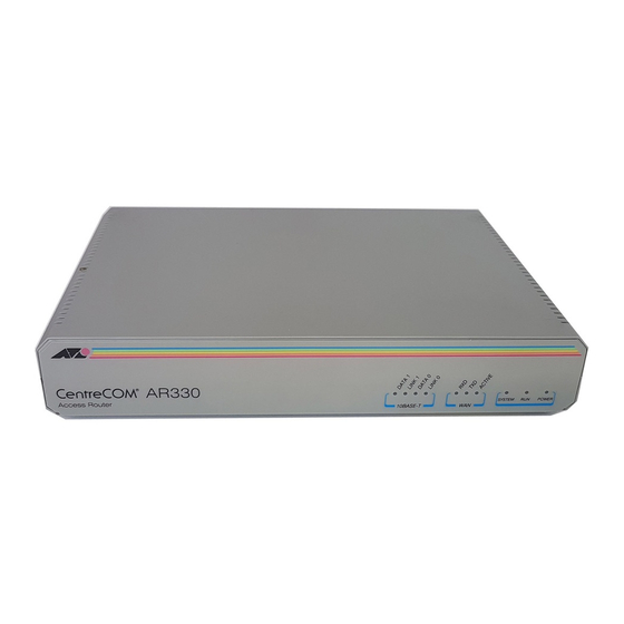
- Page 21 Hardware Reference Table 5: Functions of the front panel LEDs on the AT-AR320/AT-AR330 router. Function LAN Data 1 Lit when data is being transmitted over the Ethernet 1 interface. LAN Link 1 Lit when the Ethernet 1 interface is connected to a device (e.g., a hub), which is generating link pulses.
- Page 22 AR Router Table 6: Functions of the front panel LEDs on the AT-AR350 router. Function LAN Link Lit when the Ethernet interface is connected to a device (e.g., a hub), which is generating link pulses. This LED is normally lit. LAN Txd Lit when data is being transmitted over the Ethernet interface.
- Page 23 Hardware Reference Table 7: Functions of the front panel LEDs on the AT-AR370(S) router. Function LAN Link Lit when the Ethernet interface is connected to a device (e.g., a hub), which is generating link pulses. This LED is normally lit. LAN Txd Lit when data is being transmitted over the Ethernet interface.
- Page 24 AR Router Table 8: Functions of the front panel LEDs on the AT-AR370(U) router. Function LAN Link Lit when the Ethernet interface is connected to a device (e.g., a hub), which is generating link pulses. This LED is normally lit. LAN Txd Lit when data is being transmitted over the Ethernet interface.
-
Page 25: The Main System
Hardware Reference Table 9: Functions of the front and rear panel LEDs on the AT-AR390 and AT-AR395 routers. Function LAN Link Lit when the Ethernet interface is connected to a device (e.g., a hub), which is generating link pulses. This LED is normally lit. LAN Txd Lit when data is being transmitted over the Ethernet interface. -
Page 26: Hardware Features
AR Router Set asynchronous port default to: • 9600 bps • 8 data bits • 1 stop bit • No parity • Hardware flow control. Hardware Features All models have a DIP switch, which is located on the router’s rear panel. DIP switch functions are shown in Table 10 on page 26. - Page 27 Hardware Reference All jumpers should be left in the factory default positions unless you are advised otherwise by your authorised Allied Telesyn distributor or reseller. Jumpers should only be replaced by authorised service personnel. Unauthorised opening of the router lid may cause danger of injury from electric shock, damage to the router, and invalidation of the product warranty.
- Page 28 AR Router Figure 10: Location of main components on the AT-AR320, AT-AR320, and AT- AR330 base CPU cards. AMPLIMITE 50 WAY SYNCHRONOUS 0 RJ45 RJ45 ASYNCHRONOUS CONFIG PORTS 0 & 1 ETHERNET 0 ETHERNET 1 SYNCHRONOUS 0 CONNECTOR MAC CARD SLOT WARNING: LITHIUM BATTERY DO NOT DISPOSE IN FIRE...
- Page 29 Hardware Reference Figure 11: Location of main components on the AT-AR350 base CPU card. AMPLIMITE 50 WAY SYNCHRONOUS 0 RJ45 ASYNCHRONOUS CONFIG PORTS 0 & 1 ETHERNET 0 SYNCHRONOUS 0 CONNECTOR MAC CARD SLOT WARNING: LITHIUM BATTERY DO NOT DISPOSE IN FIRE BOOT EPROM System Power...
- Page 30 AR Router Figure 12: Location of main components on the AT-AR370(S) base CPU card. AMPLIMITE 50 WAY SYNCHRONOUS 0 RJ45 RJ45 RJ45 ASYNCHRONOUS CONFIG PORTS 0 & 1 ETHERNET 0 ISDN ISDN SYNCHRONOUS 0 CONNECTOR S/T BUS BRI 0 MAC CARD SLOT BOOT EPROM WARNING: LITHIUM BATTERY...
- Page 31 Hardware Reference Figure 13: Location of main components on the AT-AR370(U) base CPU card. AMPLIMITE 50 WAY SYNCHRONOUS 0 RJ45 RJ45 ASYNCHRONOUS CONFIG PORTS 0 & 1 ETHERNET 0 ISDN SYNCHRONOUS 0 CONNECTOR BRI 0 J1 (NT MODE) MAC CARD SLOT BOOT EPROM WARNING: LITHIUM BATTERY...
- Page 32 AR Router Figure 14: Location of main components on the AT-AR390 and AT-AR395 base CPU cards. RJ45 RJ45 120Ω J2 J3 ASYNCHRONOUS CONFIG PORTS 0 & 1 120Ω G.703/PRI ETHERNET 0 75Ω ISDN 0 GND CAP (TE/NT MODE) MAC CARD SLOT BOOT EPROM WARNING: LITHIUM BATTERY...
- Page 33 Hardware Reference For a complete description of the analogue voice port features and the commands available to configure the PABX services, see the Software Reference for your router. LAN Ports All models in the AR300 Series, except the AT-AR330, have a single Ethernet 10BASE-T LAN port.
-
Page 34: Ar400 Series Routers
AR Router Several grounding options are available for coaxial connectors. The factory default should suit all countries, but the jumper selection in Table 14 on page 32 provides flexibility. Normal practice is to ground one end only of each cable, usually the Tx cable. - Page 35 Hardware Reference The MAC slot can accommodate any one of the following MACs: • AT-AR010 EMAC, Encryption MAC. • AT-AR011 ECMAC, Compression/Encryption MAC • AT-AR011 V2 ECMAC, Compression/Encryption MAC. • AT-AR012 CMAC, Compression MAC. MACs should only be installed by authorised service personnel. Unauthorised opening of the router lid may cause danger of injury from electric shock, damage to the router, and invalidation of the product warranty.
- Page 36 AR Router Table 16: AR410 System LEDs State Function Power Green The router is receiving power and the power switch is in the ON position System Amber The Router is malfunctioning Normal operation Enabled Green A PIC card is correctly installed and has been detected by the router (PIC Bay 0) No card is installed...
-
Page 37: Ar700 Series Routers
Hardware Reference The RS-232 asynchronous serial port (ASYN 0) can be used as a general purpose port for terminals, printers or modems. The default communications settings are: • 9600 bps • 8 data bits • 1 stop bit • no parity •... -
Page 38: Ar720 Router
AR Router AR720 Router The AT-AR720 router consists of a base CPU card, enclosure and power supply. The base CPU card supports a single 10/100 autosensing Ethernet LAN port and two asynchronous RS-232 ports. The chassis has two Port Interface Card (PIC) bays, which can accommodate any combination of the following PICs: AT-AR020 PRI E1/T1 PIC, one Primary Rate E1/T1 port. - Page 39 Hardware Reference Figure 16: Front and rear panels of the AR720 Series router. Front Panel Model name AR720 STATU POWE SYSTE CLEA SECURIT Multi-Functional Remote Router LEDs Two PIC bays Rear DISCONNECT MAINS SUPPLY BEFORE REMOVING STATU ETHERNE PORT INTERFACE ENGIN ACT DAT ER CLR...
-
Page 40: Ar725 Router
AR Router The Main System Main features of the AT-AR720 base CPU card are: 50 MHz RISC processor. 1 MByte of EPROM. 16 MBytes of synchronous DRAM. 4 MBytes of flash memory, expandable to 8 MBytes for early models. 128 KBytes of battery backed SRAM. A high performance 10/100 Fast Ethernet LAN port. - Page 41 Hardware Reference In addition, the AT-AR725 router has a dedicated PAC slot, which can accommodate the following PACs: AT-AR060 EPAC, Encryption PAC. AT-AR061 ECPAC, Compression/Encryption PAC. Front and Rear Panels The AT-AR725 router’s front and rear panels (with a PIC installed in each PIC bay) are shown in Figure 17 on page 41.
- Page 42 AR Router Functions of LEDs of the AT-AR725 router. Table 19: Function Front panel Rear panel These LEDs give indications about the Ethernet interfaces.There are two LEDs for each Eth port. L/A (Link/Activity) Lit green when the Ethernet interface is connected to a device (e.g., a hub), which is generating link pulses.
-
Page 43: Ar740 Router
Hardware Reference The two asynchronous serial ports can be used as general purpose ports for terminals, printers, or modems. They are effectively identical and can be independently configured. The default communications settings are: • 9600 bps • 8 data bits •... - Page 44 AR Router Front and Rear Panels Front and rear panels of the AT-AR740 router with a PIC installed in each PIC bay, and an AT-AR040 4-PIC NSM installed in the NSM bay, are shown in Figure 18 on page 44. Figure 18: Front and rear panels of the AT-AR740 Series router.
- Page 45 Hardware Reference Table 20: Functions of AT-AR740 router LEDs. (Continued) Function System Lit when the switch or management software is malfunctioning. Flashes to indicate fan, PSU, and RPS faults. 1 Flash: A switch fan has failed. 2 Flashes: If an RPS is connected and RPS monitoring is enabled, an RPS fan has failed. 3 Flashes: If an RPS is connected, the switch’s PSU (Power Supply Unit) has failed.
- Page 46 AR Router The Main System Main features of the AT-AR740 base CPU card are: 80 MHz RISC processor. 1 MByte of EPROM. 16 MBytes of synchronous DRAM. 6 MBytes of flash memory. 128 KBytes of battery backed SRAM. 2 x 10/100 Mbps autosensing Ethernet LAN ports. 2 RS-232 asynchronous serial ports.
- Page 47 Hardware Reference The Ethernet LAN ports are autosensing 10/100 full duplex interfaces. The two asynchronous serial ports can be used as general purpose ports for terminals, printers or modems. They are effectively identical and can be independently configured. The default communications settings are: •...
-
Page 48: Ar745 Router
AR Router Redundant Power Supply (RPS) AC models of the AT-AR740 can be used in conjunction with the AT-RPS 740. Each AT-RPS 740 can provide power supply and mains circuit redundancy for up to two AT-AR740s. For more information on the AT-RPS 740, see “AT-RPS 740”... - Page 49 Hardware Reference AT-AR021(U) BRI-U PIC, one Basic Rate ISDN U port. AT-AR022 ETH PIC, one Ethernet LAN AUI/10BASE-T port. AT-AR023 SYN PIC, one Synchronous port with universal 50-way AMPLIMITE connector. AT-AR024 ASYN4 PIC, four Asynchronous ports with RJ-45 connectors. AT-AR026 4ETH PIC, four 100BASE-T/100BASE-TX ports with RJ-45 connectors.
- Page 50 AR Router Table 22: Functions of AT-AR745 router LEDs. Function Front panel Rear panel These LEDs give indications about the Ethernet interfaces. LNK/ACT Lit green when the Ethernet interface is connected to a device (e.g., a hub) which is generating link pulses. Lit yellow indicates transmission or reception activity. 100M Lit when the Ethernet interface is in 100 Mbps mode.
- Page 51 Hardware Reference The SHOW SYSTEM command displays the state of the main power supply and fan, and whether or not the RPS is being monitored. If RPS monitoring is enabled, it also shows whether an RPS is connected, and the state of its output voltage and fan.
- Page 52 AR Router Figure 22: Location of main components on the AT-AR745 base CPU card. RJ45 RJ45 PIC1 LNK/ LNK/ Swap Hot Swap PIC0 Button PORT 0 PORT 1 STATUS LEDs ETHERNET 0 ETHERNET 1 SLIDE-IN BAY 0 SLIDE-IN BAY 1 PIC BAY 0 PIC BAY 1 LITHIUM BATTERY...
- Page 53 Hardware Reference AT-AR745 AC AC models of the AT-AR745 have a universal AC input connector and a power switch on their rear panels. A DB25 connector for an optional external Redundant Power Supply (RPS), such as the AT-RPS 745, is also located on the rear panel.
-
Page 54: At-Rps 740
AR Router Table 23: DB25 RPS power connector pin out on the AT-AR745. Function Direction 1, 25 Keying 2, 14 +12V input 3-5, 15-17 input 6-8, 18-20 input -12V input output Main PSU error output Main fan error output RPS disconnected input Sense 0V output... -
Page 55: Dc Supply Cables
Hardware Reference Figure 24: Front and rear panels of the AT-RPS 740. Front panel Rear panel AC POWER 1 AC POWER 2 RPS DC OUTPUT 1 RPS STATUS ROUTER STATUS RPS DC OUTPUT 2 AC Power AC Power AC Power RPS Fan Main PSU RPS PSU... -
Page 56: Specifications
AR Router Table 24: DB25 RPS power connector pin out on AT-RPS 740. Function Direction 1, 25 Keying 2, 14 +12V output 3-5, 15-17 output 6-8, 18-20 output -12V output input Main PSU error input Main fan error input output Sense 0V input Sense +5V... -
Page 57: Leds
Hardware Reference LEDs • AC power supply • RPS fan fault • Router PSU fault • RPS PSU fault • Main (router) fan fault AC Power Supply • Universal 110/240 VAC 50/60 Hz input DC Output • 5V/6.5A • 12V/1.0A •... -
Page 58: Mini Accelerator Cards (Macs)
AR Router Mini Accelerator Cards (MACs) Mini Accelerator Cards (MACs) provide additional processing features or performance, but do not add extra physical interfaces to the router. A MAC can be installed in the dedicated MAC slot (labelled Coprocessor Interface) on all AR300 Series, AR400 Series, and AR720/AR740 routers. -
Page 59: Compression
Hardware Reference Compression MAC-based compression has the following features: Local 32-bit processor for high speed control and data transfer. Dedicated high performance 32-bit compression hardware. High compression ratio Lempel-Ziv algorithm in hardware. 2 MBytes of history memory. Support for up to 127 compression channels. Compression and decompression operations are performed by a 32-bit data compression coprocessor specifically designed for high-performance Lempel- Ziv compression applications. -
Page 60: Dual Mode
AR Router Dual Mode Throughput of an encrypted link can be dramatically increased by using data compression. To support this, ECMACs support both encryption and compression to provide a dual mode which allows combined compression and encryption operations. So that the compression phase will have the best opportunity at finding non-random data, compression occurs before encryption, in the order: compression →... -
Page 61: Compression
Hardware Reference Figure 28: Location of main components on the AT-AR061 ECPAC card. PAC Connector Hole for PAC fastner Holes for PAC fasteners Compression PAC-based compression has the following features: Local 32-bit processor for high speed control and data transfer. Dedicated high performance 32-bit compression hardware. -
Page 62: Encryption
AR Router Figure 29: Typical hardware compression ratios by file type. Compression Ratio Font Program Window Text Object Spread C source Bitmap TIFF sheet File Type CMPRATIO Encryption PAC-based encryption has the following features: Local 32-bit processor for high speed control and data transfer. Dedicated high performance 32-bit Data Encryption Standard –... -
Page 63: Flash Memory
Hardware Reference Flash Memory Flash memory is a nonvolatile reprogrammable memory storage device for router software releases, allowing upgrades to be remotely loaded from any WAN or LAN port. Flash memory is also used to store other types of data such as patches, logs and configurations. - Page 64 AR Router Figure 30: Example output from the SHOW SYSTEM command for the AT-AR720 router. Router System Status Time 17:10:06 Date 25-Sep-1999. Board Bay Board Name Serial number -------------------------------------------------------------------------------- Base AR720 M1-0 6845218 IC Module AR022 PIC Eth M2-0 6844595 IC Module AR023 PIC Sync M1-1...
-
Page 65: Interfaces
Hardware Reference Figure 32: Example output from the SHOW FILE command for an AT-AR720. creator name type size file date & time address check ----------------------------------------------------------------------------- flash inst release 15-Oct-1999 10:23:08 02723B20 flash load 52772 300236 15-Oct-1999 10:11:47 02559AC4 flash load 52-181 1575696 15-Oct-1999 10:21:48... - Page 66 AR Router Table 27: Pinout of the DB9 female connectors on asynchronous interfaces (pins are numbered from left to right). Function Signal Direction Not connected Output from router Input to router Input to router Output from router Input to router Output from router RING Input to router (only available on expansion card interfaces)
-
Page 67: Synchronous Interfaces
Hardware Reference Asynchronous interfaces follow the RS-232 standard. A range of speeds is selectable using the SET PORT command from the Interfaces chapter of your router’s Software Reference. Not all signals need to be connected. In particular, both DCD and CTS are not required unless the interface has been specifically set up to use them. -
Page 68: Ethernet Interfaces
AR Router data, while asynchronous modems don’t require a clock and rely on the inherent framing provided by the start and stop bits. Normally, any modem 9600 bps or faster will be synchronous. The router can be connected to other remote routers to form a wide area network (WAN), using synchronous modems connected to the synchronous interfaces on the router’s rear panel. -
Page 69: Basic Rate Isdn Interfaces
Hardware Reference Basic Rate ISDN Interfaces Basic Rate ISDN (BRI) interfaces support two 64K B channels and one D channel. On some routers and expansion cards the operational mode of the BRI ISDN interface (TE or NT) is determined by jumpers mounted on the CPU or expansion card. -
Page 70: Voice Ports
AR Router Table 31: Connection standard for Primary Rate ISDN BNC 75Ω connectors. Signal Connection TX-/RX- Outer conductor (i.e., shield) TX+/RX+ Inner conductor Table 32: Connection standard for Primary Rate ISDN RJ-45 120Ω connectors (from left to right, with latch down, as viewed from the rear). Signal RX ground selection from jumper TX ground selection from jumper... - Page 71 Hardware Reference AR routers support a wide range of interface types, including Ethernet, asynchronous, synchronous, Basic Rate ISDN and Primary Rate ISDN. Each interface type (except Ethernet interfaces on the AT-AR026 PIC) can be tested independently using the Test Facility software. Most tests, however, will also require the use of a loopback plug.
-
Page 72: Asynchronous Interface Tests
AR Router Asynchronous Interface Tests Asynchronous interfaces require a loopback plug to be installed before the test will operate. See “Cables And Loopback Plugs” on page 73 for details of how to make a loopback plug. To start a test of an asynchronous interface, use the command: ENABLE TEST INT=PORT n where n is the interface number. -
Page 73: Cables And Loopback Plugs
Hardware Reference Cables And Loopback Plugs This section describes how to make cables for connecting the AR router to networks, terminals, and printers. It also describes loopback plugs, which are required for testing most AR router interfaces. Transition Cables for Network Interfaces AR router synchronous ports use AMPLIMITE 50-way connectors wired as universal connectors to supp/rt RS-232/V.28, V.35 and X.21 interface standards. - Page 74 AR Router It is very important that the cables do not degrade EMC emission standards of the router (e.g., FCC, CISPR). The cable foil shield must be connected to the AMPLIMITE metalised backshell with a 360 degree ferrule. In addition, on specified cables, a clip-on cable ferrite must be attached to the cable at the AMPLIMITE end, no more than 25 mm from the rear of the backshell of the AMPLIMITE connector.
- Page 75 Hardware Reference Figure 34: Pin wiring diagram for an RS-232 DTE transition cable to an AMPLIMITE 50-way connector. D50 SCSI-2 Male D25 Male (to router) (to DCE) Insulating Sheath Cable Shield Connect to backshell Shield → (103) ← (104) → (105) ←...
- Page 76 AR Router Figure 35: Pin wiring diagram for an RS-232 DCE transition cable to an AMPLIMITE 50-way connector. D50 SCSI-2 Male D25 Female (to router) (to DTE) Insulating Sheath Cable Shield Connect to backshell Shield ← (103) → (104) ← (105) →...
- Page 77 Hardware Reference Figure 36: Pin wiring diagram for a V.35 DTE transition cable to an AMPLIMITE 50-way connector. D50 SCSI-2 Male M34 Male (to router) (to DCE) Insulating Sheath Cable Shield Connect to backshell Shield SIG G → (103) (−5V) 25 ←...
- Page 78 AR Router Figure 37: Pin wiring diagram for a V.35 DCE transition cable to an AMPLIMITE 50-way connector. D50 SCSI-2 Male M34 Female (to router) (to DTE) Insulating Sheath Cable Shield Connect to backshell Shield SIG G ← (104) → (114) →...
- Page 79 Hardware Reference Figure 38: Pin wiring diagram for an X.21 DTE transition cable to an AMPLIMITE 50-way connector. D50 SCSI-2 Male D15 Male (to router) (to DCE) Insulating Sheath Cable Shield Connect to backshell Shield Ground → Transmit → Control ←...
- Page 80 AR Router Figure 39: Pin wiring diagram for an X.21 DCE transition cable to an AMPLIMITE 50-way connector. D50 SCSI-2 Male D15 Female (to router) (to DTE) Insulating Sheath Cable Shield Connect to backshell Shield Ground ← Receive ← Indication (A) →...
-
Page 81: Isdn Interface Cables
Hardware Reference ISDN Interface Cables AR routers support two types of ISDN interface—Primary Rate Access and Basic Rate Access. Figure 40 on page 81 shows how to wire a cable to connect a Basic Rate Interface (BRI) to the ISDN network terminating equipment (NT). Figure 40: Pin wiring diagram for an ISDN Basic Rate Interface cable. - Page 82 AR Router Figure 41: Pin wiring diagram for an ISDN Primary Rate Interface (120Ω) cable. RJ45 (to switch or router) ← ← Not connected → → Not connected Not connected Not connected Notes: → Output from switch or router; ← Input to switch or router. Use Grade 5 twisted pair cable, with pairs 1 and 2, and 4 and 5.
-
Page 83: Terminal And Modem Cables
Hardware Reference Terminal and Modem Cables Table 35 on page 83 lists the wiring diagrams to follow when constructing terminal and modem cables for various connector and port combinations. Table 35: Terminal and modem cables. Cable Figure RJ-45 (router) to DB25 female (terminal) cable Figure 43 on page 83 DB9 female (router/DTE) to DB9 female (PC/terminal/DTE) cable Figure 44 on page 84... - Page 84 AR Router Figure 44: Pin wiring diagram for a standard DB9 male terminal cable. DB9 Female DB9 Female (to router/DTE) (to PC/terminal/DTE) ← (DCD) ← (RXD) → (TXD) → (DTR) Not Connected (GND) (RTS) → (CTS) Not Connected Pin 5 Pin 1 Pin 5 Pin 1...
- Page 85 Hardware Reference Figure 45: Pin wiring diagram for a standard DB9 male to female terminal cable. DB9 Male DB9 Female (to router/DCE) (to PC/terminal/DTE) (DCD) Not connected → (TXD) (RXD) ← (RXD) (TXD) ← (CD) (DTR) (GND) (GND) → (DTR) (DSR) ←...
- Page 86 AR Router Figure 46: Pin wiring diagram for a DTE asynchronous port (DB9 male) to modem (DCE) cable. DB9 Female DB9 Male (to router/DTE) (to modem/DCE) ← (DCD) (DCD) ← (RXD) (RXD) → (TXD) (TXD) → (DTR) (DTR) (GND) (GND) (DSR) Not needed Not connected →...
- Page 87 Hardware Reference Figure 47: Pin wiring diagram for a DCE asynchronous port (DB9 female connector) to modem cable. DB9 Male DB9 Male (to router/DCE) (to modem/DCE) Not connected → (TXD) 3 (TXD) ← (RXD) 2 (RXD) ← (CD) 1 (DCD) (GND) 5 (GND) →...
-
Page 88: Transceivers And Aui Cables
AR Router Figure 49: Pin wiring diagram for a Macintosh serial cable. RJ45 MiniDin (to Macintosh) (to switch or router) (RING) ← (DCD) → (RTS) ← (RXD) → (GND) ← (TXD) → (CTS) Not connected (DTR) Notes: → Output from switch or router; ← Input to switch or router. Cable version 1.0. -
Page 89: Loopback Plugs For Testing Interfaces
Hardware Reference Voice Ports and Adaptor Cables Voice ports use a standard RJ11 connector. To connect telephones with a BT- style connector, use an RJ11-to-BT adaptor cable (Figure 50 on page 89). Figure 50: Pin wiring diagram for an RJ11 to BT adaptor cable. RJ11 Plug BT Socket Pin 1... - Page 90 AR Router Table 38: Loopback plug pin wiring diagrams. Physical Interface Loopback Method/Pin Wiring Diagram RJ-45 asynchronous interface Figure 51 on page 90 DB9 Male Figure 52 on page 90 DB9 Female Figure 53 on page 91 Ethernet AUI interface Figure 54 on page 91 Ethernet TP interface Figure 55 on page 91...
- Page 91 Hardware Reference Figure 53: DB9 male loopback plug for testing asynchronous ports with DB9 female connectors. DB9 Male Asynchronous Port Loopback Plug (DB9 female connector) Pin 5 Pin 1 Pin 9 Pin 6 DB9 Female — Pin View DB9FLOOP Figure 54: Ethernet AUI loopback plug. AUI Loopback Plug (Female D15 connector) C1 = 100nF ceramic capacitor C2 = 100nF ceramic capacitor...
- Page 92 AR Router Figure 56: Primary Rate ISDN 120Ω loopback plug. PRI Loopback Plug (RJ45 connector) Switch or router end view P120LOOP Loopback Plugs for BRI Interfaces If your router or expansion option’s BRI interface has an MC145474 or MC145574 transceiver, a loopback plug is required before the BRI interface can be tested.
-
Page 93: Pics And Nsms
Hardware Reference Figure 57: Basic Rate ISDN loopback plug wiring diagram. BRI Loopback Plug (RJ45 connector) Not connected Not connected Router end view of plug Not connected Not connected BRILOOP PICs and NSMs PICs (Port Interface Cards) can be installed in some AR400 Series routers and all AR700 Series routers. -
Page 94: Installing A Mac
AR Router Installing a MAC MACs can be installed in all AR300 and AR400 series routers, and AR740 routers, one MAC per router. MACs should only be installed by authorised service personnel. Unauthorised opening of the router lid may cause danger of injury from electric shock, damage to the router, and invalidation of the product warranty. - Page 95 Hardware Reference Replace the router lid and the power cord. Secure the router’s lid. If you disconnected an RPS supply or interface cables, reconnect them now. The MAC is now ready to test. Testing a MAC There are several ways to check that the MAC is installed and operating correctly.
- Page 96 AR Router Figure 58: Example output from the SHOW SYSTEM command for an AR720 router with an AT-AR011 V2 ECMAC installed. Router System Status Time 06:58:43 Date 15-Jun-2001. Board Bay Board Name Serial number -------------------------------------------------------------------------------- Base AR720 M1-0 40272628 AT-AR020-00 PIC E1/T1 PRI M1-0 42189364 AR011 ECMAC v2...
- Page 97 Hardware Reference If any MAC tests fail, check that the MAC is correctly installed in its slot and repeat the tests. Contact your authorised Allied Telesyn distributor or reseller if the MAC does not operate correctly. Once the MAC is operating, its functionality can be tested either by using the Test Facility software, which is built into the router, or by configuring a module to use the MAC.
-
Page 98: Installing A Pac
AR Router Installing a PAC PACs can be installed in AR725, AR740, and AR745 routers, one PAC per router. PACs should only be installed by authorised service personnel. Unauthorised opening of the router’s lid may cause danger of injury from electric shock, damage to the router, and invalidation of the product warranty. - Page 99 Hardware Reference Figure 61: Location of PAC slot and pillar mounts on an AR740 base board. RJ45 RJ45 LNK/ LNK/ Swap Swap Button PORT 0 PORT 1 STATUS LEDs ETHERNET 0 ETHERNET 1 SLIDE-IN BAY 0 SLIDE-IN BAY 1 PIC BAY 0 PIC BAY 1 NSM BAY MAC CARD SLOT...
- Page 100 AR Router Testing a PAC There are several ways to check that the PAC is installed and operating correctly. First, check that the router has recognised the card. Turn on the router and enter the command: SHOW SYSTEM to display system information (Figure 58 on page 96). The first part of the display shows details of the cards installed in the router.
- Page 101 Hardware Reference Figure 62: Example output from the SHOW SYSTEM command for an AR740 router with an AT-AR061 ECPAC installed. Router System Status Time 09:28:27 Date 15-Jun-2001. Board Bay Board Name Serial number -------------------------------------------------------------------------------- Base AR740 M1-15 46689862 AT-AR022-00 PIC Eth M4-0 40239075 AT-AR026-00 PIC 10/100 Eth...
- Page 102 AR Router Figure 63: Example output from the SHOW LOG command for an AR740 router with an AT-AR061 ECPAC card installed. Date/Time S Mod Type SType Message -------------------------------------------------------------------------- 15 00:05:50 4 ENCO ENCO 7751 Found. Initialisation started 15 00:05:50 4 ENCO ENCO 7751 Initialisation Successful 15 00:05:50 7 SYS REST...
- Page 103 Hardware Reference Figure 64: Example output from the SHOW TEST command for an AR740 router with an AT-AR061 ECPAC installed. Router System Status Time 09:28:27 Date 15-Jun-2001. Board Bay Board Name Serial number -------------------------------------------------------------------------------- Base AR740 M1-15 46689862 AT-AR022-00 PIC Eth M4-0 40239075 AT-AR026-00 PIC 10/100 Eth...
-
Page 104: Installing A Flash Simm
AR Router Installing a Flash SIMM Early models of AT-AR720 routers can be upgraded from the factory default 4MB of flash memory to 8MB of flash memory by installing a 4MB 80-way Single Inline Memory Module (SIMM) stick. SIMMs should only be installed by authorised service personnel. Unauthorised opening of the router lid may cause danger of injury from electric shock, damage to the router, and invalidation of the product warranty. -
Page 105: At-Ar720 Dip Switch Settings
Hardware Reference Replace the router lid and the power cord. Secure the router’s lid. If you disconnected an RPS supply, reconnect it now. AT-AR720 Dip Switch Settings A DIP switch is used to change functional characteristics of the base CPU card. Figure 65 on page 105 shows the DIP switch’s location on the AT-AR720’s base CPU card. -
Page 106: Diagnostics
AR Router Table 39: Functions of the DIP switch on the AT-AR720 base CPU card. DIP Switch Function Default SW1-1 Reserved (should be OFF) SW1-2 Enable startup messages (ON=enable) SW1-3 Reserved (should be OFF) SW1-4 Enable show cycles (ON=enable) SW1-5 Disable data cache (ON=disable) SW1-6 Disable instruction cache (ON=disable) - Page 107 Hardware Reference Enable diagnostics mode during start-up. During the router start-up process, at the prompt: Force EPROM download (Y)? press [Ctrl/D] on the terminal to enter diagnostics mode. A banner page will be displayed on the terminal (Figure 66 on page 107). This can be used to check that the terminal is correctly connected.
-
Page 108: Replacing Boot Eproms
AR Router Replacing Boot EPROMs AR300 Series routers have one boot EPROM and AR720/AR740 routers have two boot EPROMs. Boot EPROMs contain bootstrap code, which loads the main code from a software release file in flash memory. In rare circumstances the boot EPROM(s) may need to be changed. - Page 109 Hardware Reference router base CPU board. Remove the boot EPROMs using the extraction tool. Alternatively, a small flat-bladed screwdriver can be used. If so, gently lever each end of a particular boot EPROM a few millimetres at a time until it comes free. Table 41: Diagrams showing the locations of EPROMs for each router model.
- Page 110 AR Router Figure 67: Example output from the SHOW INSTALL command. Install Release Patch ------------------------------------------------------------ Temporary Preferred flash:load\8-181.rez Default EPROM (8-1.8.1) ------------------------------------------------------------ Current install ------------------------------------------------------------ Preferred flash:load\8-181.rez ------------------------------------------------------------ Install history ------------------------------------------------------------ No Temporary install selected Preferred install selected Preferred release successfully installed ------------------------------------------------------------ Troubleshooting If the router fails to reboot or functions incorrectly, then the most likely cause is...
-
Page 111: Contacting Us
Hardware Reference Contacting Us Allied Telesyn Offices and Locations UNITED KINGDOM ITALY Tel: (+44) 1235 442500 Tel: (+39) 02 416047 Fax: (+44) 1235 442590 Fax: (+39) 02 419282 SWEDEN SPAIN Tel: 08 131414 NORWAY Tel: (+34) 91 5591055 Tel: 2211 1181 Fax: (+34) 91 5592644 DENMARK U.S.A.
Need help?
Do you have a question about the AR Series and is the answer not in the manual?
Questions and answers