
Related Manuals for Beckhoff EP6001-0002


Summary of Contents for Beckhoff EP6001-0002
- Page 1 Documentation EP6001-0002 1-channel serial interface (RS232 / RS422 / RS485) Version: Date: 2019-12-11...
-
Page 3: Table Of Contents
Status LEDs........................ 24 Digital inputs/outputs ........................ 25 3.7.1 Connector ........................ 25 3.7.2 Status LEDs........................ 25 3.7.3 Examples of external connections ................... 26 UL Requirements.......................... 27 4 Commissioning/Configuration ....................... 28 Configuration in TwinCAT........................ 28 Serial interface.......................... 29 4.2.1 Parameterization of the interface type ................ 29 EP6001-0002 Version: 1.0... - Page 4 Object description and parameterization ................. 39 Restoring the delivery state ...................... 53 Decommissioning .......................... 54 5 Appendix .............................. 55 General operating conditions...................... 55 EtherCAT Box- / EtherCAT P Box - Accessories ................ 56 General note on the introduction of the Beckhoff Identification Code (BIC) ........ 57 Support and Service ........................ 59 Version: 1.0 EP6001-0002...
-
Page 5: Foreword
EP1590927, EP1789857, EP1456722, EP2137893, DE102015105702 with corresponding applications or registrations in various other countries. ® EtherCAT is registered trademark and patented technology, licensed by Beckhoff Automation GmbH, Germany. Copyright © Beckhoff Automation GmbH & Co. KG, Germany. The reproduction, distribution and utilization of this document as well as the communication of its contents to others without express authorization are prohibited. -
Page 6: Safety Instructions
All the components are supplied in particular hardware and software configurations appropriate for the application. Modifications to hardware or software configurations other than those described in the documentation are not permitted, and nullify the liability of Beckhoff Automation GmbH & Co. KG. Personnel qualification This description is only intended for trained specialists in control, automation and drive engineering who are familiar with the applicable national standards. -
Page 7: Documentation Issue Status
HH - hardware version 01 - hardware version 01 Beckhoff Identification Code (BIC) The Beckhoff Identification Code contains additional information about the delivery state of the module: General note on the introduction of the Beckhoff Identification Code (BIC) [} 57]. EP6001-0002... -
Page 8: Product Overview
EtherCAT communication and for the power supply: • Feed • Downstream connection This enables the cabling of EtherCAT Box modules in a line structure: EtherCAT Power Fig. 1: EtherCAT Box modules: Example of cabling in a line structure Version: 1.0 EP6001-0002... -
Page 9: Introduction
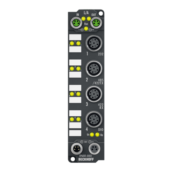
Fig. 2: EP6001-0002 EP6001-0002 | 1-channel serial interface, RS232, RS422/RS485 The EP6001-0002 serial interface module allows the connection of devices with an RS232 or RS422/RS485 interface. The module transmits the data in a fully transparent manner to the higher-level automation device. -
Page 10: Technical Data
Product overview Technical data All values are typical values at 25 °C, unless otherwise stated. Technical data EP6001-0002 Fieldbus Fieldbus EtherCAT Connection 2 x M8 socket, green Electrical isolation 500 V (fieldbus / IO) Supply voltages Connection Feed: 1 x M8 plug, 4-pin, black Downstream connection: 1 x M8 socket, 4-pin, black Control voltage U... -
Page 11: Scope Of Supply
Scope of supply Make sure that the following components are included in the scope of delivery: • 1x EtherCAT Box EP6001-0002 • 2x protective cap for EtherCAT socket, M8, green (pre-assembled) • 1x protective cap for supply voltage input, M8, transparent (pre-assembled) •... -
Page 12: Process Image
COM Inputs Status Status word [} 14] for receive data. Data In [n] The input variables "Data In 0" .. "Data In 22" each contain one byte of receive data (USINT). "Data In 0" contains the first-received byte. Version: 1.0 EP6001-0002... - Page 13 Control word [} 14] for transmit data. Data Out [n] The output variables "Data Out 0" .. "Data Out 22" can each be filled with one byte of send data. The content of "Data Out 0" is transmitted first. EP6001-0002 Version: 1.0...
-
Page 14: Control Word
Only then can new data be transferred from the box to the controller. toggle The box acknowledges the receipt of data by changing the state of this bit. Only then (TransmitAccepted) can new data be transferred from the controller to the box. Version: 1.0 EP6001-0002... -
Page 15: Technology
30 bytes per second. However, if more than these 30 bytes per second are received, a 128 bytes transmit buffer will be written to first in this case also. Once this is full, all further data will be lost. EP6001-0002 Version: 1.0... -
Page 16: Mounting And Connection
Ø 3.5 mm for M3 Metal parts brass, nickel-plated Contacts CuZn, gold-plated Power feed through max. 4 A Installation position variable Protection class IP65, IP66, IP67 (conforms to EN 60529) when screwed together Dimensions (H x W x D) approx. 126 x 30 x 26.5 mm (without connectors) Version: 1.0 EP6001-0002... -
Page 17: Fixing
Dirty connectors can lead to malfunctions. Protection class IP67 can only be guaranteed if all cables and connectors are connected. • Protect the plug connectors against dirt during the assembly. Mount the module with two M3 screws on the fastening holes in the corners of the module. The fastening holes have no thread. EP6001-0002 Version: 1.0... -
Page 18: Supply Voltages
Plug Socket Feed-in Forwarding Fig. 6: M8 connector Contact Function Description Core color Control voltage Brown Peripheral voltage White GND to U Blue GND to U Black The core colors apply to cables of the type: Beckhoff ZK2020-xxxx-xxxx Version: 1.0 EP6001-0002... -
Page 19: Status Leds
Vert. Faktor: 0,45 cm / V Vert. Faktor: 0,4 0,34 mm² Vert. Faktor: 0,45 cm / V Vert. Faktor: 0,5 mm² 0,25 mm² 0,34 mm² 0,75 mm² 0,5 mm² 0,75 mm² Cable length (m) Cable length (m) EP6001-0002 Version: 1.0... -
Page 20: Ethercat
For standardization, the core colors of the ZB9030, ZB9032 and ZK1090-3xxx-xxxx cables have been changed to the EN61918 core colors: yellow, orange, white, blue. So there are different color codes in circulation. The electrical properties of the cables have been retained when the core colors were changed. Version: 1.0 EP6001-0002... -
Page 21: Status Leds
(CAT5) according to EN 50173 or ISO/IEC 11801 should be used. EtherCAT uses four wires for signal transmission. Thanks to automatic line detection ("Auto MDI-X"), both symmetrical (1:1) or cross-over cables can be used between Beckhoff EtherCAT. Detailed recommendations for the cabling of EtherCAT devices EP6001-0002... -
Page 22: Connector
The serial port is ready to receive data. left orange illuminated The serial port is receiving data. green illuminated The serial port is ready to transmit data. right orange illuminated The serial port is transmitting data. Version: 1.0 EP6001-0002... -
Page 23: Connectors
The serial port is ready to receive data. left orange illuminated The serial port is receiving data. green illuminated The serial port is ready to transmit data. right orange illuminated The serial port is transmitting data. EP6001-0002 Version: 1.0... -
Page 24: Connector
The serial port is ready to receive data. left orange illuminated The serial port is receiving data. green illuminated The serial port is ready to transmit data. right orange illuminated The serial port is transmitting data. Version: 1.0 EP6001-0002... -
Page 25: Digital Inputs/Outputs
3.7.2 Status LEDs Fig. 18: Status LEDs for digital inputs/outputs Display Meaning Digital input/output A: Low level green illuminated Digital input/output A: High level left Digital input/output B: Low level green illuminated Digital input/output B: High level right EP6001-0002 Version: 1.0... -
Page 26: Examples Of External Connections
The signals are connected via M8 connectors (EP2xxx-0001) or M12 connectors (EP2xxx-0002). Fig. 20: Digital outputs M8 and M12 The outputs are short-circuit proof and protected against inverse polarity. LEDs indicate the signal state of the outputs. Version: 1.0 EP6001-0002... -
Page 27: Ul Requirements
To meet the UL requirements, EtherCAT Box Modules has to be operated only at an ambient temperature range of 0 to 55°C! Marking for UL All EtherCAT Box Modules certified by UL (Underwriters Laboratories) are marked with the following label. Fig. 21: UL label EP6001-0002 Version: 1.0... -
Page 28: Commissioning/Configuration
An EtherCAT Box must be configured in TwinCAT so that its functions can be used in a PLC program. The following link will take you to a quick start guide describing the configuration of an EtherCAT Box in TwinCAT: https://infosys.beckhoff.com/content/1033/epioconfiguration/index.html?id=6991403443235907429 Version: 1.0 EP6001-0002... -
Page 29: Serial Interface
Direct connection to an RS232 end device, full duplex data transmission (default setting). Fig. 22: Point-to-point connection to an RS232 device The following CoE objects must be set Index Name Meaning Data type Flags Setting F800:01 Interface Type Ch 1 0x00 RS232 BIT1 0x00 (0 (default) 0x01 RS485/422 EP6001-0002 Version: 1.0... -
Page 30: Fig. 23 4-Wire Point-To-Point Connection To An Rs422 Device
Name Meaning Data type Flags Setting 8000:07 Enable point-to- The module is used in a bus structure in accordance with the RS485 BOOLEAN point connec- standard. tion (RS422) The module is used for a point-to-point connection (RS422). Version: 1.0 EP6001-0002... -
Page 31: Fig. 24 2-Wire Connection In Bus Structure To Rs485 Device(S)
The module is used in a bus structure in accordance with the RS485 BOOLEAN point connec- standard. tion (RS422) The module is used for a point-to-point connection (RS422). Deactivated receive driver The receive driver is deactivated during the transmission procedure. The transmitted data are not monitored! EP6001-0002 Version: 1.0... -
Page 32: Fig. 25 2-Wire Connection With External Bridge In Bus Structure To Rs485 Device(S)
A conditional diagnosis of the line is thus possible. If there is a discrepancy between the transmitted data and the monitored data, it may be assumed that a further receiver also cannot re- ceive these data flawlessly. In this case, check the bus line! Version: 1.0 EP6001-0002... -
Page 33: Setting The Interface Parameters
- Differentiation between online/offline dictionary, existence of current XML description - Use "CoE reload" for resetting changes The following CoE settings are possible from object 0x8000 and are shown below in their default settings: Fig. 26: CoE settings on object 0x8000 (default) EP6001-0002 Version: 1.0... -
Page 34: Communication By Plc Program
Continuous transmission of data A continuous data stream is indispensable for many applications. For this purpose, the Beckhoff modules feature the "Enable send FIFO data continuous" setting in the Settings object. The internal transmit buffer (128 bytes) of the box can be filled first by setting this switch. After that the entire contents of the buffer can be transmitted without interruption. - Page 35 1. The module indicates that there is new data in the process image by changing the state of the "Re- ceive request" bit. 2. The number of bytes received is written in "Input length" 3. The controller acknowledges acceptance of the bytes by changing the state of “Receive request”. EP6001-0002 Version: 1.0...
-
Page 36: Communication Via A Virtual Com Port
Commissioning/Configuration 4.2.4 Communication via a virtual COM port Application Note DK9322-0411-0041 describes the communication via a virtual COM port, taking the EP6002-0002 as an example. Version: 1.0 EP6001-0002... -
Page 37: Digital Inputs/Outputs
In order to be able to use the digital inputs/outputs, you have to activate the input and output variables in the process image: ü Requirement: An EP6001-0002 has been added in the Solution Explorer under the "I/O" entry. 1. Double-click on the EP6001-0002 IO module. -
Page 38: Coe Objects
Ctrl Ch. 1 [} 51] 7010 DIG Outputs [} 51] 8000 COM Settings Ch. 1 [} 40] A000 COM Diag data Ch. 1 [} 52] F000 Modular device profile [} 52] F008 Code word [} 52] F010 Module list [} 52] F800 COM Settings [} 40] Version: 1.0 EP6001-0002... -
Page 39: Object Description And Parameterization
EtherCAT XML Device Description The display matches that of the CoE objects from the EtherCAT XML Device Description. We rec- ommend downloading the latest XML file from the download area of the Beckhoff website and in- stalling it according to installation instructions. - Page 40 Meaning Data type Flags Default F800:0 COM Settings UINT8 0x01 (1 F800:01 Interface Type Ch 1 0x00 RS232 BIT1 0x00 (0 Additional objects Standard objects (0x1000-0x1FFF) The standard objects have the same meaning for all EtherCAT slaves. Version: 1.0 EP6001-0002...
- Page 41 Index (hex) Name Meaning Data type Flags Default 1008:0 Device name Device name of the EtherCAT slave STRING EP6001-0002 Index 1009 Hardware version Index (hex) Name Meaning Data type Flags Default 1009:0 Hardware version Hardware version of the EtherCAT slave...
- Page 42 27. PDO Mapping entry (object 0x7000 (COM Outputs UINT32 0x7000:25, 8 Ch.1), entry 0x25 (Data Out 20)) 1600:1C SubIndex 028 28. PDO Mapping entry (object 0x7000 (COM Outputs UINT32 0x7000:26, 8 Ch.1), entry 0x26 (Data Out 21)) Version: 1.0 EP6001-0002...
- Page 43 0x01 (Digital Output 1)) 1608:02 SubIndex 002 2. PDO Mapping entry (object 0x7010 (DIG Outputs), UINT32 0x7010:02, 1 entry 0x02 (Digital Output 2)) 1608:03 SubIndex 003 3. PDO Mapping entry (14 bits align) UINT32 0x0000:00, 14 EP6001-0002 Version: 1.0...
- Page 44 Flags Default 1804:0 COM TxPDO-Par PDO parameter TxPDO 2 UINT8 0x06 (6 Inputs 1804:06 Exclude TxPDOs Specifies the TxPDOs (index of TxPDO mapping ob- OCTET- 00 1A jects) that must not be transferred together with TxPDO STRING[2] Version: 1.0 EP6001-0002...
- Page 45 30. PDO Mapping entry (object 0x6000 (COM Inputs UINT32 0x6000:25, 8 Ch.1), entry 0x25 (Data In 20)) 1A00:1F SubIndex 031 31. PDO Mapping entry (object 0x6000 (COM Inputs UINT32 0x6000:26, 8 Ch.1), entry 0x26 (Data In 21)) EP6001-0002 Version: 1.0...
- Page 46 0x01 (Digital Input 1)) 1A08:02 SubIndex 002 2. PDO Mapping entry (object 0x6010 (DIG Inputs), en- UINT32 0x6010:02, 1 try 0x02 (Digital Input 2)) 1A08:03 SubIndex 003 3. PDO Mapping entry (14 bits align) UINT32 0x0000:00, 14 Version: 1.0 EP6001-0002...
- Page 47 Data type Flags Default 1C13:0 TxPDO assign PDO Assign Inputs UINT8 0x02 (2 1C13:01 Subindex 001 1. allocated TxPDO (contains the index of the associ- UINT16 0x1A04 (6660 ated TxPDO mapping object) 1C13:02 Subindex 002 2. reserved UINT16 EP6001-0002 Version: 1.0...
- Page 48 Number of occasions that the interval between SYNC0 UINT16 0x0000 (0 counter and SYNC1 event was too short (DC mode only) 1C32:20 Sync error The synchronization was not correct in the last cycle BOOLEAN 0x00 (0 (outputs were output too late; DC mode only) Version: 1.0 EP6001-0002...
- Page 49 Shift too short UINT16 0x0000 (0 as 1C32:13 [} 48] counter 1C33:20 Sync error BOOLEAN 0x00 (0 as 1C32:32 [} 48] Profile-specific objects (0x6000-0xFFFF) The profile-specific objects have the same meaning for all EtherCAT slaves that support the profile 5001. EP6001-0002 Version: 1.0...
- Page 50 Data type Flags Default 6010:0 DIG Inputs UINT8 0x02 (2 6010:01 Digital Input 1 BOOLEAN 0x00 (0 6010:02 Digital Input 1 BOOLEAN 0x00 (0 6010:03 Init Accepted The initialization is carried out from the terminal BOOLEAN 0x00 (0 Version: 1.0 EP6001-0002...
- Page 51 Control word for compatible process image UINT16 0x0000 (0 Index 7010 DIG Outputs Index (hex) Name Meaning Data type Flags Default 7010:0 DIG Outputs UINT8 0x26 (38 7010:01 Digital Output 1 BOOLEAN 0x00 (0 7010:02 Digital Output 2 BOOLEAN 0x00 (0 EP6001-0002 Version: 1.0...
- Page 52 Flags Default F008:0 Code word UINT32 0x00000000 (0 Index F010 Module list Index (hex) Name Meaning Data type Flags Default F010:0 Module list UINT8 0x02 (2 F010:01 SubIndex 001 UINT32 0x00000258 (600 F010:02 SubIndex 002 UINT32 0x00000118 (280 Version: 1.0 EP6001-0002...
-
Page 53: Restoring The Delivery State
Fig. 28: Entering a restore value in the Set Value dialog Alternative restore value In some older terminals / boxes the backup objects can be switched with an alternative restore value: Decimal value: 1819238756 Hexadecimal value: 0x6C6F6164 An incorrect entry for the restore value has no effect. EP6001-0002 Version: 1.0... -
Page 54: Decommissioning
Disposal In order to dispose of the device, it must be removed. In accordance with the WEEE Directive 2012/19/EU, Beckhoff takes back old devices and accessories in Germany for proper disposal. Transport costs will be borne by the sender. Return the old devices with the note "for disposal" to: Beckhoff Automation GmbH &... -
Page 55: Appendix
(ph-Value > 12) > 40°C: not resistant Acetic acid not resistant Argon (technical clean) resistant • resistant: Lifetime several months • non inherently resistant: Lifetime several weeks • not resistant: Lifetime several hours resp. early decomposition EP6001-0002 Version: 1.0... -
Page 56: Ethercat Box- / Ethercat P Box - Accessories
M12/wrench size 13, for torque wrench ZB8801-0000 ZB8801-0003 torque cable key, M12 field assembly/wrench size 13, for torque wrench ZB8801-0000 Further accessories Further accessories may be found at the price list for Beckhoff fieldbus components and at the inter- net under https://www.beckhoff.com Version: 1.0 EP6001-0002... -
Page 57: General Note On The Introduction Of The Beckhoff Identification Code (Bic)
Identification Code (BIC) General In future you will increasingly find machine-readable information on Beckhoff products in the form of a Data Matrix Code (DMC, ECC200). This helps us to improve the quality assurance process, beyond which you can use it for better identification of our products. - Page 58 Article description Quantity An important component of the BIC is the Beckhoff Traceability Number (BTN, item no. 2). The BTN is a unique 8-character serial number that in future will replace all other serial number systems at Beckhoff (e.g. batch designations on IO components, hitherto serial number circle for safety products, etc.). The BTN is likewise being introduced gradually, so it may be the case that the BTN is not yet coded in the BIC.
-
Page 59: Support And Service
Beckhoff's branch offices and representatives Please contact your Beckhoff branch office or representative for local support and service on Beckhoff products! The addresses of Beckhoff's branch offices and representatives round the world can be found on her internet pages: http://www.beckhoff.com You will also find further documentation for Beckhoff components there. - Page 60 Table of Figures Table of Figures Fig. 1 EtherCAT Box modules: Example of cabling in a line structure ..........Fig. 2 EP6001-0002..........................Fig. 3 Level of RS232, RS422, RS485 interfaces.................. Fig. 4 Dimensions ..........................Fig. 5 Connectors for supply voltages ....................
Need help?
Do you have a question about the EP6001-0002 and is the answer not in the manual?
Questions and answers