
Related Manuals for Beckhoff EPP6001-0002


Summary of Contents for Beckhoff EPP6001-0002
- Page 1 Documentation | EN EPP6001-0002 1-channel serial interface (RS232 / RS422 / RS485) 2023-02-01 | Version: 1.3...
-
Page 3: Table Of Contents
Examples of external connections ................... 26 UL Requirements .......................... 27 Disposal ............................ 28 5 Commissioning/Configuration....................... 29 Integrating into a TwinCAT project .................... 29 Serial interface .......................... 30 5.2.1 Setting the interface type .................... 30 5.2.2 Setting the interface parameters .................. 34 EPP6001-0002 Version: 1.3... - Page 4 Version identification of EtherCAT devices .................. 58 6.3.1 General notes on marking.................... 58 6.3.2 Version identification of EP/EPI/EPP/ER/ERI boxes............ 59 6.3.3 Beckhoff Identification Code (BIC) ................... 60 6.3.4 Electronic access to the BIC (eBIC)................. 62 Support and Service........................ 64 Version: 1.3 EPP6001-0002...
-
Page 5: Foreword
, XTS and XPlanar are registered trademarks of and licensed by Beckhoff Automation GmbH. Other designations used in this publication may be trademarks whose use by third parties for their own purposes could violate the rights of the owners. Patent Pending... -
Page 6: Safety Instructions
All the components are supplied in particular hardware and software configurations appropriate for the application. Modifications to hardware or software configurations other than those described in the documentation are not permitted, and nullify the liability of Beckhoff Automation GmbH & Co. KG. Personnel qualification This description is only intended for trained specialists in control, automation and drive engineering who are familiar with the applicable national standards. -
Page 7: Documentation Issue Status
YY - year of production 10 - year of production 2010 FF - firmware version 02 - firmware version 02 HH - hardware version 01 - hardware version 01 Further information on this topic: Version identification of EtherCAT devices [} 58]. EPP6001-0002 Version: 1.3... -
Page 8: Product Group: Ethercat P Box Modules
EtherCAT P Box modules are EtherCAT P slaves with degree of protection IP67. They are designed for operation in wet, dirty or dusty industrial environments. EtherCAT basics A detailed description of the EtherCAT system can be found in the EtherCAT system documentation. Version: 1.3 EPP6001-0002... -
Page 9: Product Overview
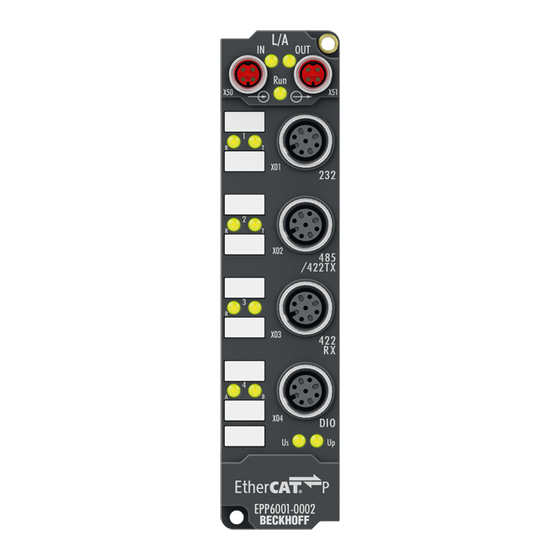
Fig. 1: EPP6001-0002 EPP6001-0002 | 1-channel serial interface, RS232, RS422/RS485 The EPP6001-0002 serial interface module allows the connection of devices with an RS232 or RS422/ RS485 interface. The module transmits the data in a fully transparent manner to the higher-level automation device. -
Page 10: Technical Data
Product overview Technical data All values are typical values over the entire temperature range, unless stated otherwise. Technical data EPP6001-0002 Fieldbus Fieldbus EtherCAT Connection EtherCAT P: Combined connection for EtherCAT and supply voltages Input: 1 x M8 socket, 4-pin, P-coded... -
Page 11: Scope Of Supply
Scope of supply Make sure that the following components are included in the scope of delivery: • 1x EtherCAT P Box EPP6001-0002 • 2x protective cap for EtherCAT P socket, M8, red (pre-assembled) • 10x labels, blank (1 strip of 10) Pre-assembled protective caps do not ensure IP67 protection Protective caps are pre-assembled at the factory to protect connectors during transport. -
Page 12: Process Image
Process image COM Inputs Status Status word for receive data. Data In [n] The input variables "Data In 0" .. "Data In 22" each contain one byte of receive data (USINT). "Data In 0" contains the first-received byte. Version: 1.3 EPP6001-0002... - Page 13 Control word for transmit data. Data Out [n] The output variables "Data Out 0" .. "Data Out 22" can each be filled with one byte of send data. The content of "Data Out 0" is transmitted first. EPP6001-0002 Version: 1.3...
-
Page 14: Control Word
Only then can new data be transferred from the box to the controller. toggle The box acknowledges the receipt of data by changing the state of this bit. Only then (TransmitAccepted) can new data be transferred from the controller to the box. Version: 1.3 EPP6001-0002... -
Page 15: Technology
A buffer is also available for the send data. With a baud rate of 300 and a data format of 8N1, the box can only transmit 30 bytes per second. However, if more than 30 byte come in per second, the send buffer is written to first in this case also. Once this is full, all further data will be lost. EPP6001-0002 Version: 1.3... -
Page 16: Mounting And Connection
Metal parts brass, nickel-plated Contacts CuZn, gold-plated Installation position variable Protection class IP65, IP66, IP67 (conforms to EN 60529) when screwed together Dimensions (H x W x D) approx. 126 x 30 x 26.5 mm (without connectors) Version: 1.3 EPP6001-0002... -
Page 17: Fixing
Fig. 3: Connection for functional earth (FE) 4.1.4 Tightening torques for plug connectors Screw connectors tight with a torque wrench. (e.g. ZB8801 from Beckhoff) Connector diameter Tightening torque 0.4 Nm 0.6 Nm... -
Page 18: Ethercat P
EtherCAT P Box to the next EtherCAT P Box in a simple manner. NOTE Note the maximum current. Ensure that the maximum permitted current of 3 A for the M8 connectors is not exceeded when redirecting EtherCAT P. Version: 1.3 EPP6001-0002... -
Page 19: Connectors
Core color Tx + yellow Rx + white Rx - : peripheral voltage, +24 V blue Tx - : control voltage, +24 V orange Housing Shield Shield Shield The core colors apply to EtherCAT P cables and ECP cables from Beckhoff. EPP6001-0002 Version: 1.3... -
Page 20: Status Leds
Each EtherCAT slave has a green LED labelled "Run". The LED signals the status of the slave in the EtherCAT network: Meaning Slave is in "Init" state flashes uniformly Slave is in "Pre-Operational“ state flashes sporadically Slave is in "Safe-Operational" state Slave is in "Operational" state Description of the EtherCAT slave states Version: 1.3 EPP6001-0002... -
Page 21: Conductor Losses
Further information can be found in the quick start guide IO configuration in TwinCAT in chapter "Configuration of EtherCAT P via TwinCAT". Voltage drop on the supply line I = 3 A 0.14 mm² 0.22 mm² Vert. Faktor: 0,22 cm / V 0.34 mm² Cable length (m) EPP6001-0002 Version: 1.3... -
Page 22: Connector
The serial port is ready to receive data. left orange illuminated The serial port is receiving data. green illuminated The serial port is ready to transmit data. right orange illuminated The serial port is transmitting data. Version: 1.3 EPP6001-0002... -
Page 23: Connectors
The serial port is ready to receive data. left orange illuminated The serial port is receiving data. green illuminated The serial port is ready to transmit data. right orange illuminated The serial port is transmitting data. EPP6001-0002 Version: 1.3... -
Page 24: Connector
The serial port is ready to receive data. left orange illuminated The serial port is receiving data. green illuminated The serial port is ready to transmit data. right orange illuminated The serial port is transmitting data. Version: 1.3 EPP6001-0002... -
Page 25: Digital Inputs/Outputs
4.6.2 Status LEDs Fig. 13: Status LEDs for digital inputs/outputs Display Meaning Digital input/output A: Low level green illuminated Digital input/output A: High level left Digital input/output B: Low level green illuminated Digital input/output B: High level right EPP6001-0002 Version: 1.3... -
Page 26: Examples Of External Connections
The signals are connected via M8 connectors (EP2xxx-0001) or M12 connectors (EP2xxx-0002). Fig. 15: Digital outputs M8 and M12 The outputs are short-circuit proof and protected against inverse polarity. LEDs indicate the signal state of the outputs. Version: 1.3 EPP6001-0002... -
Page 27: Ul Requirements
To meet the UL requirements, EtherCAT Box Modules has to be operated only at an ambient temperature range of -25 °C to +55 °C! Marking for UL All EtherCAT Box Modules certified by UL (Underwriters Laboratories) are marked with the following label. Fig. 16: UL label EPP6001-0002 Version: 1.3... -
Page 28: Disposal
Products marked with a crossed-out wheeled bin shall not be discarded with the normal waste stream. The device is considered as waste electrical and electronic equipment. The national regulations for the disposal of waste electrical and electronic equipment must be observed. Version: 1.3 EPP6001-0002... -
Page 29: Commissioning/Configuration
Commissioning/Configuration Commissioning/Configuration Integrating into a TwinCAT project The procedure for integration in a TwinCAT project is described in these Quick start guide. EPP6001-0002 Version: 1.3... -
Page 30: Serial Interface
Direct connection to an RS232 end device, full duplex data transmission (default setting). Fig. 17: Point-to-point connection to an RS232 device The following CoE objects must be set Index Name Meaning Data type Flags Setting F800:01 Interface Type Ch 1 0x00 RS232 BIT1 0x00 (0 (default) 0x01 RS485/422 Version: 1.3 EPP6001-0002... - Page 31 Name Meaning Data type Flags Setting 8000:07 Enable point-to- The module is used in a bus structure in accordance with the RS485 BOOLEAN point connec- standard. tion (RS422) The module is used for a point-to-point connection (RS422). EPP6001-0002 Version: 1.3...
- Page 32 The module is used in a bus structure in accordance with the RS485 BOOLEAN point connec- standard. tion (RS422) The module is used for a point-to-point connection (RS422). Deactivated receive driver The receive driver is deactivated during the transmission procedure. The transmitted data are not monitored! Version: 1.3 EPP6001-0002...
- Page 33 A conditional diagnosis of the line is thus possible. If there is a discrepancy between the transmitted data and the monitored data, it may be assumed that a further receiver also cannot re- ceive these data flawlessly. In this case, check the bus line! EPP6001-0002 Version: 1.3...
-
Page 34: Setting The Interface Parameters
Fig. 21: CoE settings on object 0x8000 (default) Continuous transmission of data A continuous data stream is indispensable for many applications. For this purpose, the Beckhoff modules feature the "Enable send FIFO data continuous" setting in the Settings object. The internal transmit buffer of the box can be filled first by setting this switch. -
Page 35: Communication By Plc Program
Since received data normally cannot be repeated by the transmitter, they have a higher priority in the module than data to be transmitted. Furthermore, the priority decreases as the channel number increases. Hence, the reception of data on channel 1 has the highest priority. EPP6001-0002 Version: 1.3... - Page 36 1. The module indicates that there is new data in the process image by changing the state of the "Re- ceive request" bit. 2. The number of bytes received is written in "Input length" 3. The controller acknowledges acceptance of the bytes by changing the state of “Receive request”. Version: 1.3 EPP6001-0002...
-
Page 37: Communication Via A Virtual Com Port
Commissioning/Configuration 5.2.4 Communication via a virtual COM port Application Note DK9322-0411-0041 describes the communication via a virtual COM port, taking the EP6002-0002 as an example. EPP6001-0002 Version: 1.3... -
Page 38: Digital Inputs/Outputs
In order to be able to use the digital inputs/outputs, you have to activate the input and output variables in the process image: ü Requirement: An EPP6001-0002 has been added in the Solution Explorer under the "I/O" entry. 1. Double-click on the EP6001-0002 IO module. -
Page 39: Coe Objects
Ctrl Ch. 1 [} 52] 7010 DIG Outputs [} 52] 8000 COM Settings Ch. 1 [} 41] A000 COM Diag data Ch. 1 [} 53] F000 Modular device profile [} 53] F008 Code word [} 53] F010 Module list [} 53] F800 COM Settings [} 41] EPP6001-0002 Version: 1.3... -
Page 40: Object Description And Parameterization
EtherCAT XML Device Description The display matches that of the CoE objects from the EtherCAT XML Device Description. We rec- ommend downloading the latest XML file from the download area of the Beckhoff website and in- stalling it according to installation instructions. - Page 41 Meaning Data type Flags Default F800:0 COM Settings UINT8 0x01 (1 F800:01 Interface Type Ch 1 0x00 RS232 BIT1 0x00 (0 Additional objects Standard objects (0x1000-0x1FFF) The standard objects have the same meaning for all EtherCAT slaves. EPP6001-0002 Version: 1.3...
- Page 42 Index (hex) Name Meaning Data type Flags Default 1008:0 Device name Device name of the EtherCAT slave STRING EPP6001-0002 Index 1009 Hardware version Index (hex) Name Meaning Data type Flags Default 1009:0 Hardware version Hardware version of the EtherCAT slave...
- Page 43 27. PDO Mapping entry (object 0x7000 (COM Outputs UINT32 0x7000:25, 8 Ch.1), entry 0x25 (Data Out 20)) 1600:1C SubIndex 028 28. PDO Mapping entry (object 0x7000 (COM Outputs UINT32 0x7000:26, 8 Ch.1), entry 0x26 (Data Out 21)) EPP6001-0002 Version: 1.3...
- Page 44 0x01 (Digital Output 1)) 1608:02 SubIndex 002 2. PDO Mapping entry (object 0x7010 (DIG Outputs), UINT32 0x7010:02, 1 entry 0x02 (Digital Output 2)) 1608:03 SubIndex 003 3. PDO Mapping entry (14 bits align) UINT32 0x0000:00, 14 Version: 1.3 EPP6001-0002...
- Page 45 Flags Default 1804:0 COM TxPDO-Par PDO parameter TxPDO 2 UINT8 0x06 (6 Inputs 1804:06 Exclude TxPDOs Specifies the TxPDOs (index of TxPDO mapping ob- OCTET- 00 1A jects) that must not be transferred together with TxPDO STRING[2] EPP6001-0002 Version: 1.3...
- Page 46 30. PDO Mapping entry (object 0x6000 (COM Inputs UINT32 0x6000:25, 8 Ch.1), entry 0x25 (Data In 20)) 1A00:1F SubIndex 031 31. PDO Mapping entry (object 0x6000 (COM Inputs UINT32 0x6000:26, 8 Ch.1), entry 0x26 (Data In 21)) Version: 1.3 EPP6001-0002...
- Page 47 0x01 (Digital Input 1)) 1A08:02 SubIndex 002 2. PDO Mapping entry (object 0x6010 (DIG Inputs), en- UINT32 0x6010:02, 1 try 0x02 (Digital Input 2)) 1A08:03 SubIndex 003 3. PDO Mapping entry (14 bits align) UINT32 0x0000:00, 14 EPP6001-0002 Version: 1.3...
- Page 48 Data type Flags Default 1C13:0 TxPDO assign PDO Assign Inputs UINT8 0x02 (2 1C13:01 Subindex 001 1. allocated TxPDO (contains the index of the associ- UINT16 0x1A04 (6660 ated TxPDO mapping object) 1C13:02 Subindex 002 2. reserved UINT16 Version: 1.3 EPP6001-0002...
- Page 49 Number of occasions that the interval between SYNC0 UINT16 0x0000 (0 counter and SYNC1 event was too short (DC mode only) 1C32:20 Sync error The synchronization was not correct in the last cycle BOOLEAN 0x00 (0 (outputs were output too late; DC mode only) EPP6001-0002 Version: 1.3...
- Page 50 Shift too short UINT16 0x0000 (0 as 1C32:13 [} 49] counter 1C33:20 Sync error BOOLEAN 0x00 (0 as 1C32:32 [} 49] Profile-specific objects (0x6000-0xFFFF) The profile-specific objects have the same meaning for all EtherCAT slaves that support the profile 5001. Version: 1.3 EPP6001-0002...
- Page 51 Data type Flags Default 6010:0 DIG Inputs UINT8 0x02 (2 6010:01 Digital Input 1 BOOLEAN 0x00 (0 6010:02 Digital Input 1 BOOLEAN 0x00 (0 6010:03 Init Accepted The initialization is carried out from the terminal BOOLEAN 0x00 (0 EPP6001-0002 Version: 1.3...
- Page 52 Control word for compatible process image UINT16 0x0000 (0 Index 7010 DIG Outputs Index (hex) Name Meaning Data type Flags Default 7010:0 DIG Outputs UINT8 0x26 (38 7010:01 Digital Output 1 BOOLEAN 0x00 (0 7010:02 Digital Output 2 BOOLEAN 0x00 (0 Version: 1.3 EPP6001-0002...
- Page 53 Flags Default F008:0 Code word UINT32 0x00000000 (0 Index F010 Module list Index (hex) Name Meaning Data type Flags Default F010:0 Module list UINT8 0x02 (2 F010:01 SubIndex 001 UINT32 0x00000258 (600 F010:02 SubIndex 002 UINT32 0x00000118 (280 EPP6001-0002 Version: 1.3...
-
Page 54: Restoring The Delivery State
Fig. 23: Entering a restore value in the Set Value dialog Alternative restore value In some older terminals / boxes the backup objects can be switched with an alternative restore value: Decimal value: 1819238756 Hexadecimal value: 0x6C6F6164 An incorrect entry for the restore value has no effect. Version: 1.3 EPP6001-0002... -
Page 55: Decommissioning
Commissioning/Configuration Decommissioning WARNING Risk of electric shock! Bring the bus system into a safe, de-energized state before starting disassembly of the devices! EPP6001-0002 Version: 1.3... -
Page 56: Appendix
(ph-Value > 12) > 40°C: not resistant Acetic acid not resistant Argon (technical clean) resistant • resistant: Lifetime several months • non inherently resistant: Lifetime several weeks • not resistant: Lifetime several hours resp. early decomposition Version: 1.3 EPP6001-0002... -
Page 57: Accessories
Torque cable key for M12 / wrench size 13 for ZB8801-0000 ZB8801-0003 Torque cable key for M12 field assembly / wrench size 18 for ZB8801-0000 Further accessories Further accessories can be found in the price list for fieldbus components from Beckhoff and online at https://www.beckhoff.com. EPP6001-0002 Version: 1.3... -
Page 58: Version Identification Of Ethercat Devices
Associated and synonymous with each revision there is usually a description (ESI, EtherCAT Slave Information) in the form of an XML file, which is available for download from the Beckhoff web site. From 2014/01 the revision is shown on the outside of the IP20 terminals, see Fig. “EL5021 EL terminal, standard IP20 IO device with batch number and revision ID (since 2014/01)”. -
Page 59: Version Identification Of Ep/Epi/Epp/Er/Eri Boxes
Version identification of EP/EPI/EPP/ER/ERI boxes The serial number/ data code for Beckhoff IO devices is usually the 8-digit number printed on the device or on a sticker. The serial number indicates the configuration in delivery state and therefore refers to a whole production batch, without distinguishing the individual modules of a batch. -
Page 60: Beckhoff Identification Code (Bic)
6.3.3 Beckhoff Identification Code (BIC) The Beckhoff Identification Code (BIC) is increasingly being applied to Beckhoff products to uniquely identify the product. The BIC is represented as a Data Matrix Code (DMC, code scheme ECC200), the content is based on the ANSI standard MH10.8.2-2016. - Page 61 Fig. 26: Example DMC 1P072222SBTNk4p562d71KEL1809 Q1 51S678294 An important component of the BIC is the Beckhoff Traceability Number (BTN, position 2). The BTN is a unique serial number consisting of eight characters that will replace all other serial number systems at Beckhoff in the long term (e.g.
-
Page 62: Electronic Access To The Bic (Ebic)
Electronic access to the BIC (eBIC) Electronic BIC (eBIC) The Beckhoff Identification Code (BIC) is applied to the outside of Beckhoff products in a visible place. If possible, it should also be electronically readable. Decisive for the electronic readout is the interface via which the product can be electronically addressed. - Page 63 EtherCAT, the eBIC of the top-level device is located in the CoE object directory 0x10E2:01 and the eBICs of the sub-devices follow in 0x10E2:nn. Profibus/Profinet/DeviceNet… Devices Currently, no electronic storage and readout is planned for these devices. EPP6001-0002 Version: 1.3...
-
Page 64: Support And Service
Please contact your Beckhoff branch office or representative for local support and service on Beckhoff products! The addresses of Beckhoff's branch offices and representatives round the world can be found on her internet pages: https://www.beckhoff.com You will also find further documentation for Beckhoff components there. - Page 66 More Information: www.beckhoff.com/epp6001-0002 Beckhoff Automation GmbH & Co. KG Hülshorstweg 20 33415 Verl Germany Phone: +49 5246 9630 info@beckhoff.com www.beckhoff.com...
Need help?
Do you have a question about the EPP6001-0002 and is the answer not in the manual?
Questions and answers