
Related Manuals for Beckhoff EM7004


Summary of Contents for Beckhoff EM7004
- Page 1 Documentation EM7004 4 Axis Interface, 16 Digital Inputs, 16 Digital Outputs, 4 Analog Outputs, 4 Encoder Inputs Version: Date: 2016-09-21...
-
Page 3: Table Of Contents
5.3 Standard objects (0x1000-0x1FFF) .................... 98 5.4 Profile-specific objects (0x6000-0xFFFF) .................. 107 6 Appendix .............................. 113 6.1 Ordering information for EM7004 modules and EM/KM connectors .......... 113 6.2 EtherCAT AL Status Codes ...................... 114 6.3 Firmware compatibility ........................ 114 6.4 Firmware Update EL/ES/EM/EPxxxx.................... 114 6.5 Restoring the delivery state ...................... -
Page 4: Foreword
The TwinCAT Technology is covered, including but not limited to the following patent applications and patents: EP0851348, US6167425 with corresponding applications or registrations in various other countries. ® EtherCAT is registered trademark and patented technology, licensed by Beckhoff Automation GmbH, Germany Copyright © Beckhoff Automation GmbH & Co. KG, Germany. -
Page 5: Safety Instructions
All the components are supplied in particular hardware and software configurations appropriate for the application. Modifications to hardware or software configurations other than those described in the documentation are not permitted, and nullify the liability of Beckhoff Automation GmbH & Co. KG. Personnel qualification This description is only intended for trained specialists in control, automation and drive engineering who are familiar with the applicable national standards. -
Page 6: Documentation Issue Status
• Object description added, PLS function added • Object description added • First preliminary documentation for EM7004 Version identification of EtherCAT devices Designation A Beckhoff EtherCAT device has a 14-digit designation, made up of • family key • type • version • revision... - Page 7 Production lot/batch number/serial number/date code/D number The serial number for Beckhoff IO devices is usually the 8-digit number printed on the device or on a sticker. The serial number indicates the configuration in delivery state and therefore refers to a whole production batch, without distinguishing the individual modules of a batch.
-
Page 8: Fig. 1 El5021 El Terminal, Standard Ip20 Io Device With Batch Number And Revision Id (Since 2014/01)
Foreword Examples of markings: Fig. 1: EL5021 EL terminal, standard IP20 IO device with batch number and revision ID (since 2014/01) Fig. 2: EK1100 EtherCAT coupler, standard IP20 IO device with batch number Fig. 3: CU2016 switch with batch number Version: 2.0 EM7004... -
Page 9: Fig. 4 El3202-0020 With Batch Numbers 26131006 And Unique Id-Number 204418
Fig. 5: EP1258-00001 IP67 EtherCAT Box with batch number 22090101 and unique serial number 158102 Fig. 6: EP1908-0002 IP76 EtherCAT Safety Box with batch number 071201FF and unique serial number 00346070 Fig. 7: EL2904 IP20 safety terminal with batch number/date code 50110302 and unique serial number 00331701 EM7004 Version: 2.0... -
Page 10: Product Overview
Terminal reliably meets increased requirements for I/O signals through its modularity and compact design. The existing Beckhoff Bus Terminal system is complemented by the new version of the EMxxxx / KMxxxx Terminal Modules with increased packing density. In many areas of application, cost benefits can be realized through lower overall installed size and application-specific signal mix. -
Page 11: Fig. 10 Terminal Module With Plug Connector For Single Conductor Connection Method (Zs2001-0002)
Packing density The Terminal Modules combine 16, 32 or 64 digital inputs or outputs on a very small area. This compact and slimline design enables very high packing densities, leading to smaller control cabinets and terminal boxes. EM7004 Version: 2.0... -
Page 12: Fig. 12 Terminal Module With 16 Channels
Product overview Fig. 12: Terminal module with 16 channels Fig. 13: Terminal module with 32 channels Fig. 14: Terminal module with 64 channels Version: 2.0 EM7004... -
Page 13: Introduction
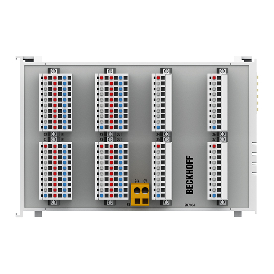
Fig. 15: EM7004 Terminal module axis interface The EtherCAT module EM7004 is an interface that is optimized for direct connection of 4 servo drives, whose "encoder simulation" feeds the module with RS485 signals. The compact module features 4 integrated incremental encoders, 16 digital 24 V inputs and outputs, and 4 analog ±10 V outputs. -
Page 14: Technical Data
Approval Basic function principles The 4-axis interface terminal module EM7004 integrates 4 Incremental encoder, 4 analog outputs with +/-10 V and 16 digital 24 V inputs and outputs. The digital inputs and outputs can be connected in single, two or three wire connection mode. -
Page 15: Analog Process Data
Output value after manufacturer calibration (the feature object user scaling [0x8020:01 [} 97] (channel 1), 0x8030:01 [} 97] (channel 2), 0x8040:01 [} 97] (channel 3), 0x8050:01 [} 97] (channel 4) is inactive] = Y x A x 2 Output value following user scaling W EM7004 Version: 2.0... - Page 16 [} 97], 0x8050:11 [} 97] User scaling gain (can be activated via feature object user scaling [0x8020:01 0x8020:12 [} 97] (channel 1), 0x8030:01 [} 97] (channel 2), 0x8040:01 [} 97] (channel [} 97], 3), 0x8050:01 [} 97] (channel 4)] 0x8030:12 [} 97], 0x8040:12 [} 97], 0x8050:12 [} 97] Version: 2.0 EM7004...
- Page 17 ("Encoder as PLS source", object 0x80A0:01 [} 98]) has reached a particular switch value ("PLS switch value", object 0x80A1 [} 111]). Object 0x80A0:11 [} 98] ("output mask") is used to specify which of the digital outputs are allocated to the PLS function. EM7004 Version: 2.0...
- Page 18 365 µs. Note Code Word Code word The vendor reserves the authority for the basic calibration of the terminals. The code word is therefore at present reserved. Note Version: 2.0 EM7004...
-
Page 19: Mounting And Wiring
2,5 mm material thickness (according to EN 60715)! Dimensions EM7004 Fig. 16: EM7004 dimensions Mounting and demounting - terminals with traction lever unlocking The terminal modules are fastened to the assembly surface with the aid of a 35 mm mounting rail (e.g. - Page 20 • Lever the unlatching hook on the left-hand side of the terminal module upwards with a screwdriver (3). As you do this ◦ an internal mechanism pulls the two latching lugs (3a) from the top hat rail back into the terminal module, ◦ the unlatching hook moves forwards (3b) and engages Version: 2.0 EM7004...
-
Page 21: Installation Positions
Attention fied. When installing high power dissipation terminals ensure that an adequate spacing is maintained between other components above and below the terminal in order to guarantee adequate ventilation! EM7004 Version: 2.0... -
Page 22: Fig. 17 Recommended Distances For Standard Installation Position
Other installation positions All other installation positions are characterized by different spatial arrangement of the mounting rail - see Fig “Other installation positions”. The minimum distances to ambient specified above also apply to these installation positions. Version: 2.0 EM7004... -
Page 23: Fig. 18 Other Installation Positions
Mounting and wiring Fig. 18: Other installation positions EM7004 Version: 2.0... -
Page 24: Wiring
X8 must not exceed 10 A (see Technical Attention data [} 14])! Version 2: Alternative 24 V module supply The diagram shows the alternative connection of the supply voltage for the digital inputs and outputs, and the further connection of the module. Version: 2.0 EM7004... -
Page 25: Fig. 20 Connection Of The Module With Alternative Power Supply
• the positive supply voltage to terminal location +24 V • the negative supply voltage to terminal location 0 V Connection for clamped joints X0 - X1 Digital inputs, channel 0 - 15 (16 channels) (with connector ZS2001-0002 or ZS2001-0004) EM7004 Version: 2.0... - Page 26 Output 0 Output 1 Output 2 Output 3 Output 4 Output 5 Output 6 Output 7 0 V 0 V 24 V Output 8 Output 9 Output 10 Output 11 Output 12 Output 13 Output 14 Output 15 0 V 0 V Version: 2.0 EM7004...
- Page 27 Analog output 3, -10 V Shield Encoder 4, input A Encoder 4, input /A Encoder 4, input B Encoder 4, input /B Encoder 4, Gate Encoder 4, Latch Ground Analog output 4, +10 V Analog output 4, -10 V Shield EM7004 Version: 2.0...
-
Page 28: Connection Technology
The digital inputs and outputs can be connected in • single-conductor (see example, terminal point 0), • two-conductor (see example, terminal point 3), or • three-conductor mode (see example, terminal point 6) Input circuits Fig. 21: Input circuits single-, two- and three-conductor mode Version: 2.0 EM7004... -
Page 29: Fig. 22 Output Circuits Single-, Two- And Three-Conductor Mode
Mounting and wiring Output circuits Fig. 22: Output circuits single-, two- and three-conductor mode EM7004 Version: 2.0... -
Page 30: Commissioning
• "offline": The configuration can be customized by adding and positioning individual components. These can be selected from a directory and configured. ◦ The procedure for offline mode can be found under http://infosys.beckhoff.com: TwinCAT 2 → TwinCAT System Manager → IO - Configuration → Adding an I/O Device •... -
Page 31: Fig. 23 Relationship Between User Side (Commissioning) And Installation
• Linked via the X001 port (RJ-45): EK1100 EtherCAT Coupler • Connected to the EK1100 EtherCAT coupler on the right (E-bus): EL2008 (8-channel digital output terminal 24 V DC; 0.5 A) • (Optional via X000: a link to an external PC for the user interface) EM7004 Version: 2.0... -
Page 32: Fig. 24 Control Configuration With An Embedded Pc And Input (El1004) And Output (El2008)
The starting point is the TwinCAT System Manager. After successful installation of the TwinCAT system on the PC to be used for development, the TwinCAT 2 System Manager displays the following user interface after startup: Fig. 25: Initial TwinCAT 2 user interface Version: 2.0 EM7004... -
Page 33: Fig. 26 Selection Of The Target System
Fig. 27: Specify the PLC for access by the TwinCAT System Manager: selection of the target system Once the target system has been entered, it is available for selection as follows (a password may have to be entered): EM7004 Version: 2.0... -
Page 34: Fig. 28 Select "Scan Devices
Confirm the message "Find new boxes", in order to determine the terminals connected to the devices. "Free Run" enables manipulation of input and output values in "Config mode" and should also be acknowledged. Based on the sample configuration [} 31] described at the beginning of this section, the result is as follows: Version: 2.0 EM7004... -
Page 35: Fig. 30 Mapping Of The Configuration In The Twincat 2 System Manager
TwinCAT PLC Control is the development environment for the creation of the controller in different program environments: TwinCAT PLC Control supports all languages described in IEC 61131-3. There are two text- based languages and three graphical languages. • Text-based languages ◦ Instruction List (IL) EM7004 Version: 2.0... -
Page 36: Fig. 32 Twincat Plc Control After Startup
The following section refers to Structured Text (ST). After starting TwinCAT PLC Control, the following user interface is shown for an initial project: Fig. 32: TwinCAT PLC Control after startup Sample variables and a sample program have been created and stored under the name "PLC_example.pro": Version: 2.0 EM7004... -
Page 37: Fig. 33 Sample Program With Variables After A Compile Process (Without Variable Integration)
Manager has been notified, the warning no longer appears. First, integrate the TwinCAT PLC Control project in the System Manager via the context menu of the PLC configuration; right-click and select "Append PLC Project…": Fig. 34: Appending the TwinCAT PLC Control project EM7004 Version: 2.0... -
Page 38: Fig. 35 Plc Project Integrated In The Plc Configuration Of The System Manager
"PLC_example" and via "Modify Link..." "Standard": Fig. 36: Creating the links between PLC variables and process objects In the window that opens, the process object for the variable “bEL1004_Ch4” of type BOOL can be selected from the PLC configuration tree: Version: 2.0 EM7004... -
Page 39: Fig. 37 Selecting Pdo Of Type Bool
The links can also be checked by selecting a "Goto Link Variable” from the context menu of a variable. The object opposite, in this case the PDO, is automatically selected: EM7004 Version: 2.0... -
Page 40: Fig. 39 Application Of A "Goto Link" Variable, Using "Main.bel1004_Ch4" As A Sample
The PLC system can then be started as described below. Starting the controller Starting from a remote system, the PLC control has to be linked with the Embedded PC over Ethernet via "Online" → “Choose Run-Time System…": Version: 2.0 EM7004... -
Page 41: Fig. 40 Choose Target System (Remote)
This results in the message "No program on the controller! Should the new program be loaded?", which should be acknowledged with "Yes". The runtime environment is ready for the program start: EM7004 Version: 2.0... -
Page 42: Fig. 41 Plc Control Logged In, Ready For Program Startup
(cf. "TwinCAT System Manager" of TwinCAT 2) for communication with the electromechanical components. After successful installation of the TwinCAT system on the PC to be used for development, TwinCAT 3 (shell) displays the following user interface after startup: Version: 2.0 EM7004... - Page 43 First create a new project via (or under "File"→“New"→ "Project…"). In the following dialog make the corresponding entries as required (as shown in the diagram): Fig. 43: Create new TwinCAT project The new project is then available in the project folder explorer: EM7004 Version: 2.0...
- Page 44 If the intention is to address the TwinCAT runtime environment installed on a PLC as development environment remotely from another system, the target system must be made known first. Via the symbol in the menu bar: expand the pull-down menu: and open the following window: Fig. 45: Selection dialog: Choose the target system Version: 2.0 EM7004...
- Page 45 The TwinCAT System Manager may first have to be set to "Config mode" via or via the menu "TwinCAT" → "Restart TwinCAT (Config mode)". Fig. 47: Select "Scan" Confirm the warning message, which follows, and select "EtherCAT" in the dialog: EM7004 Version: 2.0...
- Page 46 The whole process consists of two stages, which may be performed separately (first determine the devices, then determine the connected elements such as boxes, terminals, etc.). A scan can also be initiated by selecting "Device ..." from the context menu, which then reads the elements present in the configuration below: Version: 2.0 EM7004...
- Page 47 The following section refers to Structured Text (ST). In order to create a programming environment, a PLC subproject is added to the project sample via the context menu of "PLC" in the project folder explorer by selecting "Add New Item….": EM7004 Version: 2.0...
- Page 48 Fig. 52: Specifying the name and directory for the PLC programming environment The "Main" program, which already exists by selecting "Standard PLC project", can be opened by double- clicking on "PLC_example_project" in "POUs”. The following user interface is shown for an initial project: Version: 2.0 EM7004...
- Page 49 Commissioning Fig. 53: Initial "Main" program of the standard PLC project To continue, sample variables and a sample program have now been created: EM7004 Version: 2.0...
- Page 50 "Assignments" in the project folder explorer: Assigning variables Via the menu of an instance - variables in the "PLC” context, use the "Modify Link…" option to open a window for selecting a suitable process object (PDO) for linking: Version: 2.0 EM7004...
- Page 51 4 of the EL1004 terminal is selected for linking. In contrast, the checkbox "All types" must be ticked for creating the link for the output variables, in order to allocate a set of eight separate output bits to a byte variable. The following diagram shows the whole process: EM7004 Version: 2.0...
- Page 52 PDO, it is possible to allocate this a set of bit-standardised variables (type "BOOL"). Here, too, a "Goto Link Variable” from the context menu of a PDO can be executed in the other direction, so that the respective PLC instance can then be selected. Version: 2.0 EM7004...
- Page 53 Fig. 60: TwinCAT development environment (VS shell): logged-in, after program startup The two operator control elements for stopping and logout result in the required action (accordingly also for stop "Shift + F5", or both actions can be selected via the PLC menu). EM7004 Version: 2.0...
-
Page 54: Twincat 2
4.2.1 Installation of the TwinCAT real-time driver In order to assign real-time capability to a standard Ethernet port of an IPC controller, the Beckhoff real-time driver has to be installed on this port under Windows. This can be done in several ways. One option is described here. - Page 55 Alternatively an EtherCAT-device can be inserted first of all as described in chapter Offline configuration creation, section “Creating the EtherCAT device” [} 65] in order to view the compatible ethernet ports via its EtherCAT properties (tab „Adapter“, button „Compatible Devices…“): EM7004 Version: 2.0...
- Page 56 After the installation the driver appears activated in the Windows overview for the network interface (Windows Start → System Properties → Network) Fig. 65: Windows properties of the network interface A correct setting of the driver could be: Version: 2.0 EM7004...
- Page 57 Commissioning Fig. 66: Exemplary correct driver setting for the Ethernet port Other possible settings have to be avoided: EM7004 Version: 2.0...
- Page 58 DHCP. In this way the delay associated with the DHCP client for the Ethernet port assigning itself a default IP address in the absence of a DHCP server is avoided. A suitable address space is 192.168.x.x, for example. Version: 2.0 EM7004...
- Page 59 Commissioning Fig. 68: TCP/IP setting for the Ethernet port EM7004 Version: 2.0...
-
Page 60: Notes Regarding Esi Device Description
The files are read (once) when a new System Manager window is opened, if they have changed since the last time the System Manager window was opened. A TwinCAT installation includes the set of Beckhoff ESI files that was current at the time when the TwinCAT build was created. - Page 61 1018 in the configuration. This is also stated by the Beckhoff compatibility rule. Refer in particular to the chapter ‘General notes on the use of Beckhoff EtherCAT IO components’ and for manual configuration to the chapter ‘Offline configuration creation’ [} 65].
- Page 62 Faulty ESI file If an ESI file is faulty and the System Manager is unable to read it, the System Manager brings up an information window. Fig. 74: Information window for faulty ESI file (left: TwinCAT 2; right: TwinCAT 3) Version: 2.0 EM7004...
- Page 63 Commissioning Reasons may include: • Structure of the *.xml does not correspond to the associated *.xsd file → check your schematics • Contents cannot be translated into a device description → contact the file manufacturer EM7004 Version: 2.0...
-
Page 64: Twincat Esi Updater
Commissioning 4.2.3 TwinCAT ESI Updater For TwinCAT 2.11 and higher, the System Manager can search for current Beckhoff ESI files automatically, if an online connection is available: Fig. 75: Using the ESI Updater (>= TwinCAT 2.11) The call up takes place under: “Options” → "Update EtherCAT Device Descriptions"... -
Page 65: Offline Configuration Creation
EL6601/EL6614 terminal select “EtherCAT Automation Protocol via EL6601”. Fig. 78: Selecting the EtherCAT connection (TwinCAT 2.11, TwinCAT 3) Then assign a real Ethernet port to this virtual device in the runtime system. Fig. 79: Selecting the Ethernet port EM7004 Version: 2.0... - Page 66 Fig. “Selection dialog for new EtherCAT device”. If the preceding device has several free ports (e.g. EK1122 or EK1100), the required port can be selected on the right-hand side (A). Overview of physical layer • “Ethernet”: cable-based 100BASE-TX: EK couplers, EP boxes, devices with RJ45/M8/M12 connector Version: 2.0 EM7004...
- Page 67 (i.e. highest) revision and therefore the latest state of production is displayed in the selection dialog for Beckhoff devices. To show all device revisions available in the system as ESI descriptions tick the “Show Hidden Devices” check box, see Fig. “Display of previous revisions”.
- Page 68 If current ESI descriptions are available in the TwinCAT system, the last revision offered in the selection dialog matches the Beckhoff state of production. It is recommended to use the last device revision when creating a new configuration, if current Beckhoff devices are used in the real application. Older revisions should only be used if older devices from stock are to be used in the application.
- Page 69 Commissioning Fig. 86: EtherCAT terminal in the TwinCAT tree (left: TwinCAT 2; right: TwinCAT 3) EM7004 Version: 2.0...
-
Page 70: Online Configuration Creation
Fig. 88: Scan Devices (left: TwinCAT 2; right: TwinCAT 3) This scan mode attempts to find not only EtherCAT devices (or Ethernet ports that are usable as such), but also NOVRAM, fieldbus cards, SMB etc. However, not all devices can be found automatically. Version: 2.0 EM7004... - Page 71 [} 75] with the defined initial configura- tion.Background: since Beckhoff occasionally increases the revision version of the deliv- ered products for product maintenance reasons, a configuration can be created by such a scan which (with an identical machine construction) is identical according to the device list;...
- Page 72 Likewise, A might create spare parts stores worldwide for the coming series-produced machines with EL2521-0025-1018 terminals. After some time Beckhoff extends the EL2521-0025 by a new feature C. Therefore the FW is changed, outwardly recognizable by a higher FW version and a new revision -1019. Nevertheless the new device naturally supports functions and interfaces of the predecessor version(s);...
- Page 73 Fig. 98: Displaying of “Free Run” and “Config Mode” toggling right below in the status bar Fig. 99: TwinCAT can also be switched to this state by using a button (left: TwinCAT 2; right: TwinCAT 3) The EtherCAT system should then be in a functional cyclic state, as shown in Fig. “Online display example”. EM7004 Version: 2.0...
- Page 74 The connections and devices should be checked in a targeted manner, e.g. via the emergency scan. Then re-run the scan. Fig. 101: Faulty identification In the System Manager such devices may be set up as EK0000 or unknown devices. Operation is not possible or meaningful. Version: 2.0 EM7004...
- Page 75 A ‘ChangeTo’ or ‘Copy’ should only be Attention carried out with care, taking into consideration the Beckhoff IO compatibility rule (see above). The device configuration is then replaced by the revision found; this can affect the supported process data and functions.
- Page 76 If current ESI descriptions are available in the TwinCAT system, the last revision offered in the selection dialog matches the Beckhoff state of production. It is recommended to use the last device revision when creating a new configuration, if current Beckhoff devices are used in the real application. Older revisions should only be used if older devices from stock are to be used in the application.
- Page 77 This function is preferably to be used on AX5000 devices. If called, the System Manager suggests the devices that it finds in the associated sub-folder; in the case of the AX5000, for example, in \TwinCAT\IO \EtherCAT\Beckhoff AX5xxx. Change to Alternative Type The TwinCAT System Manager offers a function for the exchange of a device: Change to Alternative Type Fig. 107: TwinCAT 2 Dialog Change to Alternative Type...
-
Page 78: Ethercat Subscriber Configuration
Comment Here you can add a comment (e.g. regarding the system). Disabled Here you can deactivate the EtherCAT device. Create symbols Access to this EtherCAT slave via ADS is only available if this control box is activated. Version: 2.0 EM7004... - Page 79 CANopen process data objects (Process Data Objects, PDOs). The user can select a PDO via PDO assignment and modify the content of the individual PDO via this dialog, if the EtherCAT slave supports this function. EM7004 Version: 2.0...
- Page 80 For Beckhoff EtherCAT EL, ES, EM, EJ and EP slaves the following applies in general: • The input/output process data supported by the device are defined by the manufacturer in the ESI/XML description.
- Page 81 (CoE) or Servo drive over EtherCAT protocol. This tab indicates which download requests are sent to the mailbox during startup. It is also possible to add new mailbox requests to the list display. The download requests are sent to the slave in the same order as they are shown in the list. EM7004 Version: 2.0...
- Page 82 (CoE) protocol. This dialog lists the content of the object list of the slave (SDO upload) and enables the user to modify the content of an object from this list. Details for the objects of the individual EtherCAT devices can be found in the device-specific object descriptions. Version: 2.0 EM7004...
- Page 83 The object can be read, and data can be written to the object (read/write) The object can be read, but no data can be written to the object (read only) An additional P identifies the object as a process data object. Value Value of the object EM7004 Version: 2.0...
- Page 84 Offline - via EDS File If this option button is selected, the list of the objects included in the object list is read from an EDS file provided by the user. Version: 2.0 EM7004...
- Page 85 Indicates the current state of the EtherCAT device. Requested State Indicates the state requested for the EtherCAT device. DLL Status Indicates the DLL status (data link layer status) of the individual ports of the EtherCAT slave. The DLL status can have four different states: EM7004 Version: 2.0...
- Page 86 • DC-Synchron Advanced Settings… Advanced settings for readjustment of the real time determinant TwinCAT- clock Detailed information to Distributed Clocks are specified on http://infosys.beckhoff.com: Fieldbus Components → EtherCAT Terminals → EtherCAT System documentation → EtherCAT basics → Distributed Clocks 4.2.7.1...
- Page 87 If this check box is selected, the PDO assignment that is configured in the PDO Assignment list is downloaded to the device on startup. The required commands to be sent to the device can be viewed in the Startup [} 81] tab. EM7004 Version: 2.0...
-
Page 88: General Notes - Ethercat Slave Application
See the corresponding device documentation The colors in Fig. “Selection of the diagnostic information of an EtherCAT Slave” also correspond to the variable colors in the System Manager, see Fig. “Basic EtherCAT Slave Diagnosis in the PLC”. Version: 2.0 EM7004... - Page 89 Fig. “Basic EtherCAT Slave Diagnosis in the PLC” shows an example of an implementation of basic EtherCAT Slave Diagnosis. A Beckhoff EL3102 (2-channel analogue input terminal) is used here, as it offers both the communication diagnosis typical of a slave and the functional diagnosis that is specific to a channel.
- Page 90 The CoE parameter directory (CanOpen-over-EtherCAT) is used to manage the set values for the slave concerned. Changes may, in some circumstances, have to be made here when commissioning a relatively complex EtherCAT Slave. It can be accessed through the TwinCAT System Manager, see Fig. “EL3102, CoE directory”: Version: 2.0 EM7004...
- Page 91 Commissioning interfaces are being introduced as part of an ongoing process for EL/EP EtherCAT devices. These are available in TwinCAT System Managers from TwinCAT 2.11R2 and above. They are integrated into the System Manager through appropriately extended ESI configuration files. EM7004 Version: 2.0...
- Page 92 The target state wanted by the user, and which is brought about automatically at start-up by TwinCAT, can be set in the System Manager. As soon as TwinCAT reaches the status RUN, the TwinCAT EtherCAT Master will approach the target states. Version: 2.0 EM7004...
- Page 93 Fig. 122: Default behaviour of the System Manager In addition, the target state of any particular Slave can be set in the "Advanced Settings" dialogue; the standard setting is again OP. Fig. 123: Default target state in the Slave EM7004 Version: 2.0...
- Page 94 The pre-calculated theoretical maximum E-Bus current is displayed in the TwinCAT System Manager as a column value. A shortfall is marked by a negative total amount and an exclamation mark; a power feed terminal is to be placed before such a position. Version: 2.0 EM7004...
- Page 95 Fig. 126: Warning message for exceeding E-Bus current Caution! Malfunction possible! The same ground potential must be used for the E-Bus supply of all EtherCAT terminals in a terminal block! Attention EM7004 Version: 2.0...
-
Page 96: Object Description And Parameterization
EtherCAT XML Device Description The display matches that of the CoE objects from the EtherCAT XML Device Description. We recommend downloading the latest XML file from the download area of the Beckhoff Note website and installing it according to installation instructions. -
Page 97: Objects For Commissioning
Index 80nE AO Internal data Ch.1 - 4 (for 2 ≤ n ≤ 5) Index (hex) Name Meaning Data type Flags Default 80nE:0 AO Internal data Ch.1 Maximum subindex UINT8 0x01 (1 80nE:01 DAC raw value DAC raw value INT16 0x0000 (0 EM7004 Version: 2.0... -
Page 98: Objects For Regular Operation
0x0000 (0 but less than the first entry in the table), this value is out- Objects for regular operation The EM7004 has no such objects. Standard objects (0x1000-0x1FFF) The standard objects have the same meaning for all EtherCAT slaves. Index 1000 Device type... - Page 99 Index (hex) Name Meaning Data type Flags Default 1008:0 Device name Device name of the EtherCAT slave STRING EM7004 Index 1009 Hardware version Index (hex) Name Meaning Data type Flags Default 1009:0 Hardware version Hardware version of the EtherCAT slave...
- Page 100 Index (hex) Name Meaning Data type Flags Default 1605:0 AO RxPDO-Map Ch.4 PDO Mapping RxPDO 6 UINT8 0x01 (1 1605:01 SubIndex 001 1. PDO Mapping entry (object 0x7050 (AO Outputs UINT32 0x7050:11, 16 Ch.4), entry 0x11 (Analog output)) Version: 2.0 EM7004...
- Page 101 Ch.3), entry 0x04 (Enable latch extern on negative edge)) 1608:05 SubIndex 005 5. PDO Mapping entry (12 bits align) UINT32 0x0000:00, 12 1608:06 SubIndex 006 6. PDO Mapping entry (object 0x7080 (ENC Outputs UINT32 0x7080:11, 16 Ch.3), entry 0x11 (Set counter value)) EM7004 Version: 2.0...
- Page 102 0x0000:00, 1 1A00:0F SubIndex 015 15. PDO Mapping entry (object 0x6000 (DI Inputs), entry UINT32 0x6000:0F, 1 0x0F (Input 14)) 1A00:10 SubIndex 016 16. PDO Mapping entry (object 0x6000 (DI Inputs), entry UINT32 0x6000:10, 1 0x10 (Input 15)) Version: 2.0 EM7004...
- Page 103 SubIndex 012 12. PDO Mapping entry (object 0x6070 (ENC Inputs UINT32 0x6070:11, 16 Ch.2), entry 0x11 (Counter value)) 1A07:0D SubIndex 013 13. PDO Mapping entry (object 0x6070 (ENC Inputs UINT32 0x6070:12, 16 Ch.2), entry 0x12 (Latch value)) EM7004 Version: 2.0...
- Page 104 0x60A0:01, 1 try 0x01 (PLS Enabled)) 1A0A:02 SubIndex 002 2. PDO Mapping entry (object 0x60A0 (PLS Inputs), en- UINT32 0x60A0:02, 1 try 0x02 (Unequal SI:0)) 1A0A:03 SubIndex 003 3. PDO Mapping entry (14 bits align) UINT32 0x0000:00, 14 Version: 2.0 EM7004...
- Page 105 (6664 1C13:05 SubIndex 005 5. allocated TxPDO (contains the index of the associated UINT16 0x1A09 TxPDO mapping object) (6665 1C13:06 SubIndex 006 6. allocated TxPDO (contains the index of the associated UINT16 0x1A0A TxPDO mapping object) (6666 EM7004 Version: 2.0...
- Page 106 Shift too short counter Number of occasions that the interval between SYNC0 UINT16 0x0000 (0 and SYNC1 event was too short (DC mode only) 1C32:20 Sync error The synchronization was not correct in the last cycle BOOLEAN 0x00 (0 (outputs were output too late; DC mode only) Version: 2.0 EM7004...
-
Page 107: Profile-Specific Objects (0X6000-0Xffff)
Shift too short counter as 0x1C32:13 [} 106] UINT16 0x0000 (0 1C33:20 Sync error BOOLEAN 0x00 (0 as 0x1C32:32 [} 106] Profile-specific objects (0x6000-0xFFFF) The profile-specific objects have the same meaning for all EtherCAT slaves that support the profile 5001. EM7004 Version: 2.0... - Page 108 TxPDO Toggle The TxPDO toggle is toggled by the slave when the data BOOLEAN 0x00 (0 of the associated TxPDO is updated. 6070:11 Counter value Counter value UINT16 0x0000 (0 6070:12 Latch value Latch value UINT16 0x0000 (0 Version: 2.0 EM7004...
- Page 109 PLS Inputs Maximum subindex UINT8 0x02 (2 60A0:01 PLS Enabled PLS function enabled BOOLEAN 0x00 (0 60A0:02 Unequal SI:0 BOOLEAN 0x00 (0 Bit is set if the subindex 0 of indices 0x80A1 [} 111] and 0x80A2 [} 111] are different EM7004 Version: 2.0...
- Page 110 7060:04 Enable latch extern The external latch is enabled with a negative edge BOOLEAN 0x00 (0 on negative edge 7060:11 Set counter value Value of the counter value to be set via 0x7060:03 [} 110] UINT16 0x0000 (0 Version: 2.0 EM7004...
- Page 111 Default 80A2:0 PLS Output data Maximum subindex UINT8 0x00 (0 80A2:01 SubIndex 001 Switch value 1 UINT16 0x0000 (0 80A2:4A SubIndex 074 Switch value 74 UINT16 0x0000 (0 80A2:4B SubIndex 075 Switch value 75 UINT16 0x0000 (0 EM7004 Version: 2.0...
- Page 112 UINT32 0x000001FF (511 F010:09 SubIndex 009 Incremental Encoder Input Profil (510) UINT32 0x000001FF (511 F010:0A SubIndex 010 Incremental Encoder Input Profil (510) UINT32 0x000001FF (511 F010:0B SubIndex 011 Programmable Limit Switch (PLS) Profil (511) UINT32 0x00000200 (512 Version: 2.0 EM7004...
-
Page 113: Appendix
Appendix Appendix Ordering information for EM7004 modules and EM/KM connectors The following tables show the combination options and ordering information for the modules and connectors. Order identifier enclosed EM/KM connectors EM7004-0000 none EM7004-0002 4x ZS2001-0002; 4x ZS2001-0005 EM7004-0004 4x ZS2001-0004; 4x ZS2001-0005 Fig. 127: EM / KM connector ZS2001-0002... -
Page 114: Ethercat Al Status Codes
Check on the Beckhoff web page whether more up-to-date documentation is available. Firmware Update EL/ES/EM/EPxxxx This section describes the device update for Beckhoff EtherCAT slaves from the EL/ES, EM, EK and EP series. A firmware update should only be carried out after consultation with Beckhoff support. - Page 115 EtherCAT communication is set up accordingly. The device description is available from the download area of the Beckhoff website at (http://www.beckhoff.de). All ESI files are accessible there as zip files. Customers can access the data via the EtherCAT fieldbus and its communication mechanisms. Acyclic mailbox communication or register access to the ESC is used for updating or reading of these data.
- Page 116 Corresponding updates Note should only be carried out in consultation with Beckhoff support. Display of ESI slave identifier The simplest way to ascertain compliance of configured and actual device description is to scan the EtherCAT boxes in TwinCAT mode Config/FreeRun: Fig. 131: Scan the subordinate field by right-clicking on the EtherCAT device in Config/FreeRun mode...
- Page 117 The ESI/EEPROM identifier can be updated as follows under TwinCAT: • Trouble-free EtherCAT communication must be established with the slave. • The state of the slave is irrelevant. • Right-clicking on the slave in the online display opens the EEPROM Update dialog, Fig. "EEPROM Update" EM7004 Version: 2.0...
- Page 118 Determining the firmware version Determining the version on laser inscription Beckhoff EtherCAT slaves feature serial numbers applied by laser. The serial number has the following structure: KK YY FF HH KK - week of production (CW, calendar week)
- Page 119 • offline: The EtherCAT Slave Information ESI/XML may contain the default content of the CoE. This CoE directory can only be displayed if it is included in the ESI (e.g. "Beckhoff EL5xxx.xml"). The Advanced button must be used for switching between the two views.
- Page 120 Appendix Fig. 137: Firmware Update Proceed as follows, unless instructed otherwise by Beckhoff support. • Switch slave to INIT (A) • Switch slave to BOOTSTRAP • Check the current status (B, C) • Download the new *efw file • After the download switch to INIT, then OP •...
- Page 121 Fig. 139: Context menu Properties The Advanced Settings dialog appears where the columns to be displayed can be selected. Under Diagnosis/Online View select the '0002 ETxxxx Build' check box in order to activate the FPGA firmware version display. EM7004 Version: 2.0...
- Page 122 Updating an EtherCAT device In the TwinCAT System Manager select the terminal for which the FPGA firmware is to be updated (in the example: Terminal 5: EL5001) and click the Advanced Settings button in the EtherCAT tab. Version: 2.0 EM7004...
- Page 123 Appendix Fig. 141: Select dialog Advanced Settings The Advanced Settings dialog appears. Under ESC Access/E²PROM/FPGA click on Write FPGA button, Fig. 142: Select dialog Write FPGA EM7004 Version: 2.0...
- Page 124 The firmware and ESI descriptions of several devices can be updated simultaneously, provided the devices have the same firmware file/ESI. Fig. 144: Multiple selection and firmware update Select the required slaves and carry out the firmware update in BOOTSTRAP mode as described above. Version: 2.0 EM7004...
-
Page 125: Restoring The Delivery State
Fig. 146: Entering a restore value in the Set Value dialog Alternative restore value In some older terminals the backup objects can be switched with an alternative restore value:Decimal value: "1819238756", Hexadecimal value: "0x6C6F6164"An incorrect entry Note for the restore value has no effect. EM7004 Version: 2.0... -
Page 126: Support And Service
Beckhoff's branch offices and representatives Please contact your Beckhoff branch office or representative for local support and service on Beckhoff products! The addresses of Beckhoff's branch offices and representatives round the world can be found on her internet pages: http://www.beckhoff.com You will also find further documentation for Beckhoff components there. - Page 127 Terminal module with 32 channels ....................Fig. 14 Terminal module with 64 channels ....................Fig. 15 EM7004 ............................Fig. 16 EM7004 dimensions ........................Fig. 17 Recommended distances for standard installation position ............Fig. 18 Other installation positions ......................Fig. 19 Clamped joint for power supply ....................
- Page 128 Display of device revision ......................Fig. 84 Display of previous revisions ...................... Fig. 85 Name/revision of the terminal ...................... Fig. 86 EtherCAT terminal in the TwinCAT tree (left: TwinCAT 2; right: TwinCAT 3)......Fig. 87 Differentiation local/target system (left: TwinCAT 2; right: TwinCAT 3)........Version: 2.0 EM7004...
- Page 129 Fig. 129 EM / KM connector ZS2001-0005 ....................113 Fig. 130 Device identifier consisting of name EL3204-0000 and revision -0016 ........116 Fig. 131 Scan the subordinate field by right-clicking on the EtherCAT device in Config/FreeRun mode . 116 EM7004 Version: 2.0...
- Page 130 Fig. 143 Select file ............................ 124 Fig. 144 Multiple selection and firmware update ..................124 Fig. 145 Selecting the "Restore default parameters" PDO ............... 125 Fig. 146 Entering a restore value in the Set Value dialog ................. 125 Version: 2.0 EM7004...
Need help?
Do you have a question about the EM7004 and is the answer not in the manual?
Questions and answers