
Subscribe to Our Youtube Channel
Related Manuals for Meinberg IMS-PZF180


Summary of Contents for Meinberg IMS-PZF180
- Page 1 MANUAL IMS-PZF180 Setup Guide Hot-Plug Module 31st January 2020 Meinberg Funkuhren GmbH & Co. KG...
-
Page 3: Table Of Contents
........Date: 31st January 2020 IMS-PZF180 Setup Guide... - Page 4 1 Imprint 1 Imprint Meinberg Funkuhren GmbH & Co. KG Lange Wand 9, 31812 Bad Pyrmont / Germany Phone: + 49 (0) 52 81 / 93 09 - 0 Fax: + 49 (0) 52 81 / 93 09 - 230 Internet: https://www.meinbergglobal.com...
-
Page 5: Safety Instructions For Hot Pluggable Modules
• Place the module out of the box or after removal from the system with the component side to the top on a grounded and static-free surface. • Storage of an IMS module must be done in a dry place. • Installation or removal from hot-swap components only by authorized personnel! Date: 31st January 2020 IMS-PZF180 Setup Guide... -
Page 6: Additional Safety Hints
To ensure safe operation supply mains connected to this decice must be equipped with a fuse and a fault- current circuit breaker according to the applicable national standards for safe operation. The device must be connected to a protective earth with low grounding resistance according to the applicable national rules. IMS-PZF180 Setup Guide Date: 31st January 2020... -
Page 7: Cabling
Wiring or any other work done the connectors particularly when connectors are opened may never be carried out when the installation is energized. All connectors must be covered to prevent from accidental contact to life parts. ALWAYS ENSURE A PROPER INSTALLATION! Date: 31st January 2020 IMS-PZF180 Setup Guide... -
Page 8: Replacement Or Installation Of A Hot-Pluggable Ims Module
Make sure that the module is securely locked into the connector block before you fasten the two screws. Now you can put the installed module into operation. Attachment points of an 1U IMS system IMS-PZF180 Setup Guide Date: 31st January 2020... -
Page 9: Important Hints For Hot-Pluggable Ims Modules
"System". not "hot swappable" The central management unit must be disconnected from mains before replacement. RSC/SPT not "hot swappable" The RSC switching card must be disconnected from the mains before the replacement. Date: 31st January 2020 IMS-PZF180 Setup Guide... -
Page 10: Pzf - Dcf77 Long Wave Receiver
The PZF radio clock is a precision receiver system for the time signal transmitter DCF77. It is available as a module for use in systems such as Meinberg IMS, LANTIME M300 models and as a computer plug-in card. The microprocessor of the system performs the correlation of a reproduced pseudo-random bit sequence with the PZF of the transmitter side and simultaneously decodes the AM time and date information of the DCF telegram. - Page 11 AM signal - provided this is still receivable. The correlation receiver has a battery-buffered hardware clock, which takes over the time and date in the event of failure of the supply voltage. Date: 31st January 2020 IMS-PZF180 Setup Guide...
-
Page 12: Long Wave Signal Reception
DC current, an extra power supply is required in this case at the location of the antenna. Longwave receiver equipment from Meinberg has specifically been designed for Meinberg devices and is not necessarily compatible with receivers from 3rd party manufacturers. -
Page 13: Mounting And Installation Of A Longwave Antenna
Cable ca. 1,5 mm Ø fastened at the surge protector Figure: Longwave antenna mounted on a wall. The optional surge protector keeps high voltage strikes through the antenna cable away from the receiver. Date: 31st January 2020 IMS-PZF180 Setup Guide... - Page 14 - Do not carry out any work on the antenna system or the antenna cable if there is a risk of a lightning strike. - Do not carry out any work on the antenna system if the safety distance to free lines and sequential circuits is exceeded. IMS-PZF180 Setup Guide Date: 31st January 2020...
-
Page 15: Dcf77 / Pzf Receiver
100 or higher. If no correlation with the incoming signal is possible then the clock changes automatically to DCF77 AM reception mode and tries to decode the second marks. Date: 31st January 2020 IMS-PZF180 Setup Guide... -
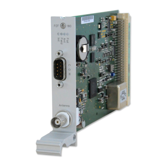
Page 16: Pzf Clock
Field: green: minimum field strength needed for the correlation receiption is detected Ant Fail: red: antenna faulty or not connected Fail: red: time is not synchronized IMS-PZF180 Setup Guide Date: 31st January 2020... - Page 17 Pin Assignment of the DSUB9 Connectors (male): Pin 2: RxD Pin 3: TxD Pin 5: GND Synchronization with PPS + String: Pin 1: PPS Pin 2: RxD Date: 31st January 2020 IMS-PZF180 Setup Guide...
-
Page 18: Menu Clock In The Web Interface
The current status of the clock can be monitored in the submenu "Receiver information". Detailed information about the LANTIME web interface can be found in the current firmware manual, which can be downloaded from our website: https://www.meinbergglobal.com/english/docs/ IMS-PZF180 Setup Guide Date: 31st January 2020...
Need help?
Do you have a question about the IMS-PZF180 and is the answer not in the manual?
Questions and answers