
Related Manuals for Meinberg IMS-PIO180


Summary of Contents for Meinberg IMS-PIO180
- Page 1 MANUAL IMS-PIO180 Setup Guide Hot-Plug Module 6th May 2020 Meinberg Funkuhren GmbH & Co. KG...
-
Page 3: Table Of Contents
..........8 Status Monitoring of the IMS-PIO180 The SyncMon . -
Page 4: Imprint
1 Imprint 1 Imprint Meinberg Funkuhren GmbH & Co. KG Lange Wand 9, 31812 Bad Pyrmont / Germany Phone: + 49 (0) 52 81 / 93 09 - 0 Fax: + 49 (0) 52 81 / 93 09 - 230 Internet: https://www.meinbergglobal.com... -
Page 5: Introduction
M3000, which can log and analyze the accuracy of up to 40 PPS signals of external systems with the help of the SyncMon, which acts as a central measurement system with a PIO180 module. Date: 6th May 2020 IMS-PIO180 Setup Guide... -
Page 6: Safety Instructions For Hot Pluggable Modules
• Place the module out of the box or after removal from the system with the component side to the top on a grounded and static-free surface. • Storage of an IMS module must be done in a dry place. • Installation or removal from hot-swap components only by authorized personnel! IMS-PIO180 Setup Guide Date: 6th May 2020... -
Page 7: Additional Safety Hints
Unload yourself (for example, by touching a grounded object) before touching assemblies. Ensure that you wear a grounding strap on the wrist when working with such assemblies, which you attach to an unpainted, non-conductive metal part of the system. Date: 6th May 2020 IMS-PIO180 Setup Guide... - Page 8 ESD protective covers, which are extremely wrinkled or even have holes, no longer protect against electrostatic discharge. ESD protective covers must not be low-resistance and metallically conductive if a lithium battery is installed on the assembly. IMS-PIO180 Setup Guide Date: 6th May 2020...
-
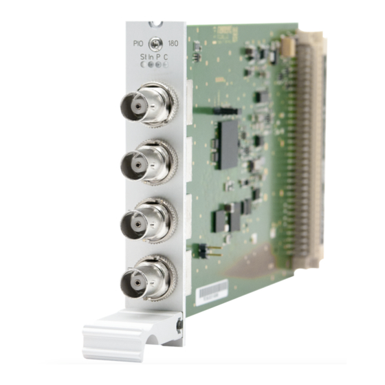
Page 9: Front Connectors Ims-Pio180
4 Front Connectors IMS-PIO180 Date: 6th May 2020 IMS-PIO180 Setup Guide... -
Page 10: Status Leds
4 Front Connectors IMS-PIO180 4.1 Status LEDs Status Indicators LED St: PIO status LED In: Status of the backplane’s output signals LED P: display for preset PPS St In P C LED C: display for preset 10 MHz Initialisation: LED St: blue until USB is configured LED In - LED B: off... -
Page 11: Before You Start
5 Before you start 5.1 Scope of Delivery Carefully unpack the IMS-PIO180 and put it aside. Check the scope of delivery with the packing list to ensure that no parts are missing. If any of the listed contents are missing, please contact Meinberg. -
Page 12: Disposal Of Packaging Materials
Before installing the PIO180 module, select the required signal using the jumper setting (PPS or 10 MHz). Upon delivery all ports are preset to PPS (Pulse Per Second). Mixed operation is not possible. All inputs/outputs are set to either PPS or 10 MHz IMS-PIO180 Setup Guide Date: 6th May 2020... -
Page 13: System Installation
"System". not "hot swappable" The central management unit must be disconnected from mains before replacement. RSC/SPT not "hot swappable" The RSC switching card must be disconnected from the mains before the replacement. Date: 6th May 2020 IMS-PIO180 Setup Guide... -
Page 14: Replacement Or Installation Of A Hot-Pluggable Ims Module
Make sure that the module is securely locked into the connector block before you fasten the two screws. Now you can put the installed module into operation. Attachment points of an 1U IMS system IMS-PIO180 Setup Guide Date: 6th May 2020... -
Page 15: Connecting The System
SyncMon zur Signalüberwachung / SyncMon for signal monitoring PPS-Signal PPS-Signal Sync to: PPS der PIO180 / PPS of the PIO180 Figure: Measurement of the PPS signal of DUT (Devices Under Test) accuracy using the PIO180 module Date: 6th May 2020 IMS-PIO180 Setup Guide... -
Page 16: Configuration Of The Ims-Pio180
7 Configuration of the IMS-PIO180 7 Configuration of the IMS-PIO180 This chapter explains how to put a IMS-PIO180 into operation via the web interface. 7.1 Menu IO Config In the "IO Config" menu of the web interface, each port of the PIO180 can be set separately to "Input"... -
Page 17: Status Monitoring Of The Ims-Pio180
8 Status Monitoring of the IMS-PIO180 This chapter describes the status monitoring of the IMS-PIO180 via the web interface. The submenu "Status" of the "IO Config" allows you to view the status of each port of installed PIO180 modules. 8.1 The SyncMon When using the PIO180 as an input module, the SyncMon offers extensive possibilities of status monitoring. - Page 18 8 Status Monitoring of the IMS-PIO180 PPS Offset The measured difference between the PPS input signal and the PPS of the reference clock can be displayed as a value or as a graph. To display the graph of the respective port, click on the ICON "Graph".
-
Page 19: Rohs And Weee
Any transportation expenses for return- ing this product (at its end of life) have to be incurred by the end user, whereas Meinberg will bear the costs for the waste disposal itself. Date: 6th May 2020...
Need help?
Do you have a question about the IMS-PIO180 and is the answer not in the manual?
Questions and answers