Table of Contents
Advertisement
Quick Links
Advertisement
Table of Contents

Related Manuals for CommScope ION-U EU H 7P/80-85P/17P/19P


Summary of Contents for CommScope ION-U EU H 7P/80-85P/17P/19P
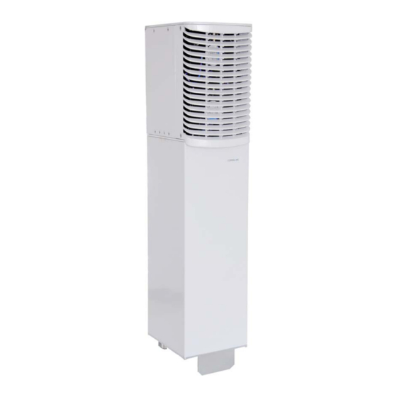
- Page 1 ® EU H 7P/80-85P/17(E)P/19P Extension Unit Manual MF0200A9D...
- Page 2 DISCLAIMER: This document has been developed by CommScope, and is intended for the use of its customers and customer support personnel. The information in this document is subject to change without notice. While every effort has been made to eliminate errors, CommScope disclaims liability for any difficulties arising from the interpretation of the information contained herein.
-
Page 3: Table Of Contents
USED ABBREVIATIONS 6 1.2. HEALTH AND SAFETY 7 1.3. PROPERTY DAMAGE WARNINGS 7 1.4. COMPLIANCE 8 1.5. ABOUT COMMSCOPE 11 1.6. INTERNATIONAL CONTACT ADDRESSES FOR CUSTOMER SUPPORT 12 INTRODUCTION 2.1. PURPOSE 14 2.2. ION-U HIGH POWER REMOTE AND EXTENSION UNITS 14 ... - Page 4 Table of Contents ALARMS 5.1. BITE AND ALARMS 41 5.2. TROUBLESHOOTING 41 5.3. STATUS LED ALARMS 41 MAINTENANCE 6.1. GENERAL 42 6.2. REPLACING THE FAN UNIT 43 6.3. CLEANING THE HEAT SINK 44 APPENDIX 7.1. ...
- Page 5 Figures and Tables FIGURES AND TABLES figure 3-1 ION-U High Power EU block diagram ............15 figure 4-1 Maximum distance between RU and EU ........... 18 figure 4-2 Wall mounting – pitches ................19 figure 4-3 Pole mounting – pitches ................20 ...
-
Page 6: General
1. General 1. General 1.1. Used Abbreviations AC/DC Alternating current / Direct Current Noise Figure AIMOS Andrew Integrated Management and Operating System Operations Maintenance Automatic Level Control Center OTRx Optical Transceiver SRMU BITE Built-In Test Equipment (Subrack Master Unit) Base Transceiver Station Passive Intermodulation Input power CDMA... -
Page 7: Health And Safety
1. General 1.2. Health and Safety 1. Danger: Electrical hazard. Danger of death or fatal injury from electrical current. Obey all general and regional installation and safety regulations relating to work on high voltage installations, as well as regulations covering correct use of tools and personal protective equipment. 2. -
Page 8: Compliance
1. General 8. Notice: Only license holders for the respective frequency range are allowed to operate this unit. 9. Notice: Make sure the repeater settings are correct for the intended use (refer to the manufacturer product information) and regulatory requirements are met. Do not carry out any modifications or fit any spare parts, which are not sold or recommended by the manufacturer. - Page 9 1. General 4. Notice: For installations which have to comply with FCC/Industry Canada requirements: English : This device complies with FCC Part 15 and Industry Canada license exempt RSS standard(s). Operation is subject to the following two conditions: (1) this device may not cause interference, and (2) this device must accept any interference, including interference that may cause undesired operation of the device.
- Page 10 1. General 7. Note: For a Class A digital device or peripheral: This equipment has been tested and found to comply with the limits for a Class A digital device, pursuant to part 15 of the FCC Rules. These limits are designed to provide reasonable protection against harmful interference when the equipment is operated in a commercial environment.
-
Page 11: About Commscope
* In case the Declaration of Conformity (DoC) for the product was not included in the manual CD delivered, it is available upon request from the local sales offices or directly from CommScope at one of the addresses listed in the following chapter. -
Page 12: International Contact Addresses For Customer Support
1. General 1.6. International Contact Addresses for Customer Support Canada United States CommScope Canada Andrew LLC, A CommScope Company 505 Consumers Road, Suite 803 620 North Greenfield Parkway Mail Mail Toronto M2J 4V8, Canada Garner, NC 27529, U.S.A. +1-905-878-3457 (Office) - Page 13 E-mail wisupport.ch@commscope.com Italy Iberia Region – Spain & Portugal CommScope Italy S.r.l., Faenza, Italy Andrew España S.A. A CommScope Company Via Mengolina, 20 Avda. de Europa, 4 – 2ª pta. Mail 48018 Faenza (RA) Mail Parque Empresarial de la Moraleja...
-
Page 14: Introduction
2. Introduction 2. Introduction 2.1. Purpose Mobile telephone and public safety systems transmit signals in two directions between base transceiver station (BTS) and mobile stations (MS) within the signal coverage area to carry voice and data traffic. If weak signal transmissions occur within the coverage area because of indoor applications, topological conditions or distance from the transmitter, extension of the transmission range can be achieved by means of an optical distributed antenna system (DAS). -
Page 15: Functional Description
3. Functional Description 3. Functional Description figure 3-1 ION-U High Power EU block diagram In the Downlink (DL) path, the Extension Unit provides: Automatic Gain Control (AGC) of each converted signal to compensate for optical losses RF amplification of the converted RF signal for transmission while maintaining an excellent signal-to-noise ratio ... -
Page 16: Commissioning
One of the three mounting kits has to be ordered separately. They are not contained within the standard equipment. See chapter 7.3 Spare Parts. Unless otherwise agreed to in writing by CommScope, CommScope’s general limited product warranty (http://www.commscope.com/Resources/Warranties/) shall be the warranty governing the Extension Units, including the installation, maintenance, usage and operation of the Extension Units. - Page 17 4. Commissioning 5. Notice: Ensure that there is free access to the electrical connections as well as to the cabinet. The approved bending radius of the connected cables must not be exceeded. See chapter 7.1 for more details. 6. Notice: If any different or additional mounting material is used, ensure that the mounting remains as safe as the mounting designed by the manufacturer.
-
Page 18: Mounting Distance Between Ru And Eu
4. Commissioning 4.2.3. Mounting distance between RU and EU The Extension Unit has to be connected to the Remote Unit via cable bridge. The length of the cable bridge determines the maximum mounting distance between the Remote Unit and the Extension Unit. Length Distance 420 mm... -
Page 19: Wall Mounting Procedure
4. Commissioning 4.2.4. Wall mounting procedure Notice: It is the responsibility of the installer to verify that the supporting surface will safely support the combined load of the electronic equipment and all attached hardware and components and to ensure that the EU is safely and securely mounted. -
Page 20: Pole Mounting Procedure With Screw Bands
4. Commissioning 4.2.5. Pole mounting procedure with screw bands Standard mounting hardware cannot be used to mount the Extension Unit to a pole, a column, or other similar structures. Additional hardware must be used for this type of installation. The pole-mounting kit includes ... -
Page 21: Pole Mounting Procedure With Brackets
4. Commissioning 3. Hang the Extension Unit into the upper bracket, insert it into the lower bracket, and fasten it to the lower bracket with the M8x25 screws ©, split lock washers (D) and washers (E), see chapter 4.2.4. The maximum diameter of the pole or column must not exceed 120 mm (4.7 inch). figure 4-6 Pole mounting –... -
Page 22: Figure 4-8 Pole Mounting - Pitches
4. Commissioning figure 4-8 Pole figure 4-9 Pole figure 4-10 Pole mounting – fasten mounting – pitches mounting – brackets 1. Apply this procedure to both mounting brackets on both sides: Screw a hexagon nut (E) to the threaded bolt and place a flat washer (F)) on it. Insert this side of the bolt into the mounting bracket (A). -
Page 23: Electrical Installation
8. Notice: Use an appropriate torque wrench for the coupling torques: for 7/16 DIN-type (25 N-m / 19 ft lb) with 1 ¼ in opening, e. g. item no. 244377 available from the CommScope e-catalog for 4.3-10 type connectors (5 N-m, 44 in lb) with 22 mm (7/8) in opening, e.g. -
Page 24: Connections
4. Commissioning 4.3.3. Connections The ION-U EU ports and connectors shown below are located at the base of the EU. figure 4-11 ION-U EU H 7P/80-85P/17(E)P/19P AC version connector flange ® Page 24 User’s Manual for ION... - Page 25 4. Commissioning ION-U High Power EU Connectors/Indicators Port/Conn Purpose Type This connector is used to interconnect to the Radiall Opus Remote Unit to provide additional bands of M424400- EXPANSION coverage. This connector is used for transmitting and 4.3-10 type receiving signals to and from an antenna, female antenna splitter, or cross-band coupler.
-
Page 26: Figure 4-12 Ion-U Eu H 7P/80-85P/17(E)P/19P Dc Version Connector Flange
4. Commissioning figure 4-12 ION-U EU H 7P/80-85P/17(E)P/19P DC version connector flange ION-U High Power EU Connectors/Indicators Port/Conn Purpose Type The connectors and indicators for the AC and the All, except DC version are identical except for the MAINS MAINS connector. -
Page 27: Grounding (Earthing)
4. Commissioning 4.3.4. Grounding (Earthing) The EU must be grounded (earthed). When double grounding lugs are used they must support M6 studs with a stud hole spacing of 15.88 mm (5/8”). Connect an earth-bonding cable to one or both of the grounding bolt connections provided on the connector flange of the Extension Unit. -
Page 28: Connection Of The Antenna Cable
Use an appropriate torque wrench for the coupling torques: for 7/16 DIN-type (25 N-m / 19 ft lb) with 1 ¼ in opening, e. g. item no. 244377 available from the CommScope e-catalog - for 4.3-10 type connectors (5 N-m, 44 in lb) with 22 mm (7/8) in opening, e.g. -
Page 29: Cleaning Procedure For Rf Cable Connectors
4. Commissioning 4.3.5.1. Cleaning procedure for RF cable connectors The figures in this chapter illustrate the cleaning procedure and do not show the actual EU. 1. What is needed for the cleaning? a. Isopropyl alcohol b. Compressed air c. Lint-free wipe d. - Page 30 4. Commissioning 5. Clean the lip of the inner ring with a cotton bud drenched with isopropyl alcohol. 6. Clean the inside surface of the inner ring with a cotton bud drenched with isopropyl alcohol. 7. Clean the inside of the center conductor spring tines with a cotton bud drenched with isopropyl alcohol.
- Page 31 4. Commissioning 9. Remove metal chips and small particles from the mating and inner surfaces of the connector using compressed air. 10. Continue with the winding area using lint-free wipe drenched with isopropyl alcohol. 11. Continue with the inside mating surface of the inner ring.
-
Page 32: Antenna Cable Connector Assembly
4. Commissioning 4.3.5.2. Antenna cable connector assembly 1. What is needed for the connector assembly? a. Torque wrench. b. (Adjustable) counter wrench 2. Join the connectors and turn the coupling nut until the thread grips. 3. Push in the connector until it clicks. 4. -
Page 33: Mains Power Connection
4. Commissioning 5. Retain the cable connector with the counter wrench and fasten the coupling nut with the Torque wrench torque wrench until the torque is applied (torque wrench clicks). Counter wrench For angled antenna connectors use your hand to retain the cable connector and fasten the coupling nut with the torque wrench. -
Page 34: Figure 4-15 Mains Power Connector
4. Commissioning Pin PE Pin1 Pin3 Pin2 figure 4-15 Mains power connector figure 4-16 Mains power cable – AC The Mains cable is part of the delivery. It’s available in two wiring configurations: Prot ect ive C ap Wiring 1 Wiring 2 Name Color... -
Page 35: Mains Power Connection Dc
4. Commissioning 4.3.6.2. Mains power connection DC Caution: Danger of electrical hazard by high current. Disconnect mains power before opening the DC connector housing. Note: The Mains cable must be properly secured observing local regulations and electrical codes. Be sure to allow enough slack in the cable at the EU to mount or dismount the cable into the DC Mains connector of the EU. - Page 36 4. Commissioning First, install conduit fitting (not contained in scope of delivery) to the 34.52 mm hole. This must be a suitable fitting for a 1 Inch conduit with lock nut. Inside, the clearance around the hole is 5 mm, the maximum space for the nut is 8 mm.
-
Page 37: Extension Unit Port Connection
4. Commissioning 4.3.7. Extension Unit port connection The EU connector is used to connect a cable bridge to the Remote Unit. This port provides control and RF signaling to and from the Extension Unit. 7-Pin Assignment n.c. System Bus RF (if Pin installed) System Bus n.c. -
Page 38: Coupling Probe
4. Commissioning Connector coupler Pin-holder figure 4-19 Mounting the EU cable bridge Take the cable bridge connector at the Then take cable bridge connector coupler and insert it carefully to the connector (Pin-holder) and push it EU connector. Use the green markings to align into the EU connector until the lock the connector, turn it without pressure until the clicks. -
Page 39: Commissioning Flow-Chart
4. Commissioning 4.4. Commissioning Flow-Chart ® User’s Manual for ION Page 39... - Page 40 4. Commissioning ® Page 40 User’s Manual for ION...
-
Page 41: Alarms
5. Alarms 5. Alarms 5.1. Bite and Alarms The Built-In Test concept comprises the monitoring of the power supplies, the power amplifiers, and fan units. All occurring alarms can be checked via software at the Master Unit. As soon as the software acknowledges a valid alarm, a message is transmitted to the Master Unit. -
Page 42: Maintenance
In order to maintain the warranty, avoid unintentional damage to the seals on the modules. Unless otherwise agreed to in writing by CommScope, CommScope’s general limited product warranty (http://www.commscope.com/Resources/Warranties/) shall be the warranty governing the Extension Units, including the installation, maintenance, usage and operation of the Extension Units. -
Page 43: Replacing The Fan Unit
6. Maintenance 6.2. Replacing the Fan Unit Replacement of the fan unit is not required as a preventative measure. Only when an alarm indicates a malfunctioning of a fan, must the unit be exchanged. Note: Please observe that the fan unit can only be replaced as a whole. Do not remove the fans separately. -
Page 44: Cleaning The Heat Sink
6. Maintenance 6.3. Cleaning the Heat Sink Note: Read and observe chapter 1.2 Health and Safety as well as the instructions in chapter 6.1 General before starting with the replacement procedure. Then, proceed as follows: 1. Switch off the Extension Unit. Make sure that mains power is disconnected for the following procedure. -
Page 45: Appendix
7. Appendix 7. Appendix 7.1. Illustrations 1 76 Airf low Power IN C able C able bridge to R em ot e U nit figure 7-1 ION-U EU H 7P/80-85P/17(E)P/19P required space ® User’s Manual for ION Page 45... -
Page 46: Specifications
This manual is valid for the following Extension Units: ID No Denomination 7698401-xxxx* ION-U EU H 7P/80-85P/17P/19P 7698401-0001 ION-U EU H 7P/80-85P/17P/19P AC 7698401-0002 ION-U EU H 7P/80-85P/17P/19P DC 7698401-0003 ION-U EU H 7P/80-85P/17EP/19P AC 7698401-0004 ION-U EU H 7P/80-85P/17EP/19P DC * The xxxx suffix is the identifier for the specific configuration of the Extension Unit. -
Page 47: Index
Cleaning the Heat Sink .......... 44 Pole with brackets ..........21 Commissioning Pole with screw bands ........20 General .............. 16 Wall ..............19 CommScope ............11 Compliance .............. 8 P Connections Antenna ............. 28 Pole Mounting ..........20, 21 Connector Panel ..........
Need help?
Do you have a question about the ION-U EU H 7P/80-85P/17P/19P and is the answer not in the manual?
Questions and answers