
Related Manuals for Svantek SVAN 971


Summary of Contents for Svantek SVAN 971
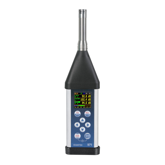
- Page 1 USER MANUAL SVAN 971 POCKET-SIZE SOUND LEVEL METER & ANALYSER Copyright © 2018 SVANTEK. All rights reserved. Warsaw, 28-03-2018...
- Page 2 Information in this document is subject to change without notice and does not represent a commitment on the part of Svantek. Svantek provides this document “as is”, without warranty of any kind, either expressed or implied, including, but not limited to, its particular purpose. Svantek reserves the right to make improvements and/or changes to this manual, or to the products and/or the programs described in this manual, at any time.
-
Page 3: Table Of Contents
SVAN 971 User Manual CONTENTS INDEX ................................8 INTRODUCTION ............................11 SVAN 971 & A ..................11 OUND EVEL ETER NALYSER SVAN 971 ......................12 ENERAL FEATURES OF ......................... 12 CCESSORIES INCLUDED ........................12 CCESSORIES AVAILABLE ) ................13 NSTRUMENT... - Page 4 SVAN 971 User Manual – S ..................42 TATISTICAL LEVELS SETTINGS TATISTICAL EVELS ’ – T ................ 42 ROGRAMMING THE INSTRUMENT S INTERNAL TIMER IMER 5.10 ........................ 42 XAMPLE OF TIMER EXECUTION CONFIGURING DATA VIEWING – DISPLAY ....................44 – D .....................
- Page 5 SVAN 971 User Manual – W ......................58 ARNINGS SELECTION ARNINGS PRINTING REPORTS - REPORT ......................59 10.1 – P ....................59 RINTING MEASUREMENT RESULTS RINT 10.2 – O ....................61 ELECTING PRINTING OPTIONS PTIONS 10.3 – R ................... 61...
- Page 6 ATE AND TIME APPENDIX C. TECHNICAL SPECIFICATIONS ....................143 SVAN 971 ................143 PECIFICATION OF AS SOUND LEVEL METER C.1.1 Specification of SVAN 971 as SLM in the standard configuration ..........143 C.1.2 Effect of the SA 22 windscreen ...................... 162...
- Page 7 SVAN 971 User Manual C.1.3 Effect of the SA 271 Outdoor Protection Unit ................. 164 SVAN 971 1/1 O 1/3 O ............ 165 PECIFICATION OF CTAVE AND CTAVE ANALYZER .............. 176 REQUENCY CHARACTERISTICS OF THE IMPLEMENTED DIGITAL FILTERS SVAN 971 ..................178...
-
Page 8: Index
SVAN 971 User Manual INDEX Display Scale · 51, 70 Dosimeter · 29, 72 Dosimeter results · 74 Dosimeter Results · 52 Downloading · 28 1/1 Octave · 29, 67 Dynamics · 52, 70 1/3 Octave · 29, 67 Environment compensation · 46 3 Profiles view ·... - Page 9 SVAN 971 User Manual Post-trigger · 40 Power Off · 59 Powering · 23 Key Lock · 58 Pre-trigger · 40, 45 Keyboard · 58 Print · 63 Print Options · 64 Print Spectrum · 65 Print Statistics · 65 Printer ·...
- Page 10 SVAN 971 User Manual ULT Threshold Level · 73 Voice comments · 61 Unit Label · 60 Uploading · 28 Usb · 59 User interface · 21 User Interface · 57 Warnings · 62 Weighting filter · 72 Windscreen compensation · 46...
-
Page 11: Introduction
Sound Level Meter (SLM) and real time 1/1 & 1/3 octave analyser. The new user interface of this instrument makes measurement configuration as easy as possible. This all makes SVAN 971 an ideal choice for industrial hygiene noise measurements, short period... -
Page 12: Eneral Features Of
• SV 75 RS232 interface option with external power supply plug for SVAN 971 • SC 91/5 extension cable for SV 18 (SVAN 971), 5 meters (for laboratory purposes) • SA 72 carrying case for SVAN 971 and accessories (waterproof) •... -
Page 13: Instrument Software Options Available ( Firmware )
SVAN 971 User Manual 1.5 I NSTRUMENT OFTWARE OPTIONS AVAILABLE FIRMWARE • SVAN 971PACK Level Meter including time history logging, 1/1 & 1/3 octave analysis • SV 971_1 1/1 octave analysis option • SV 971_3 1/1 & 1/3 octave analysis option •... -
Page 14: Manual Control Of The Instrument
SVAN 971 User Manual 2 MANUAL CONTROL OF THE INSTRUMENT Control of the instrument has been developed in a fully interactive manner. The user can operate the instrument by selecting the appropriate position from the screen Menu list. Thanks to that, the number of the control keys of the instrument has been reduced to eight for ease of use and convenience. -
Page 15: Input And Output Sockets Of The Instrument
SVAN 971 User Manual • select the parameter value in an active position (e.g. filter Z, A or C, Integration period: 1s, 2s, 3s, … etc.); • control the cursor in Spectrum, Logger and Statistics modes of result presentation; • select the position of the character in the text edition screens;... - Page 16 SVAN 971 User Manual The USB Device 2.0 interface is the serial interface working with 12 MHz clock in the full speed mode and with 480MHz in the high-speed mode, which is a default mode of the instrument. Thanks to its speed, it is widely used in all PCs.
-
Page 17: General Information
SVAN 971 User Manual 3 GENERAL INFORMATION To start using the instrument the user should turn it on with the <Shift> and <Start/Stop> keys at the same time. ’ 3.1 B ASIS OF THE INSTRUMENT S CONTROL The instrument is controlled by means of eight keys on the keypad. Using these keys, one can access all available functions and change the value of all available parameters. - Page 18 SVAN 971 User Manual Main menu The main menu (Menu) contains headers of seven sections, which contain another sub-menu. The main menu is opened after pressing the <Menu> (<Shift> and <Enter>) key. Recent Items list Double-pressing of the <Menu> key opens the list of recently used menu items.
-
Page 19: Powering Of The Instrument
Logging positions become not active! 3.2 P OWERING OF THE INSTRUMENT SVAN 971 can be powered by one of the following sources: • Four AAA standard size batteries fitted internally. In the case of alkaline type, a new fully charged set can operate more than 12 h (6.0 V / 1.6 Ah). -
Page 20: Getting Started
SVAN 971 User Manual For each power source, there is a different view presented in the Battery window of the Instrument list. When the instrument is powered from internal batteries, the “Battery” icon is presented on the top line of the display. When voltage of the batteries is too low for reliable measurements, the icon is red or during attempt to switch the instrument on, the Low Battery! message occurs on the display for 2 seconds and the instrument switches off by itself. -
Page 21: Description Of Icons
SVAN 971 User Manual profiles and summary results saving. Other functions are switched off, like: measurement trigger, logger trigger, event recording and timer. The logger and summary results will be automatically saved in the file with the name presented in the Logger Setup list (Logger Name: Lxxxx). -
Page 22: Data Saving
SVAN 971 User Manual start after pressing <Start> key due to a Grey colour of the icon means that the start delay or a delay caused by a trigger. instrument waits for the logging start after pressing <Start> key due to a start delay or a delay caused by a trigger. - Page 23 Files are saved in the directory, which was set up as a working directory. The default working directory (after using Factory Settings function) is called SVANTEK. Note: During the measurement run with data logging to the logger file, the “curve” icon is displayed.
-
Page 24: Files Downloading And Uploading
SVAN 971 User Manual Saving setup files Setup files stored means Setup Manager or from the measurement screen with the <P/S> key (<Shift> pressed together with <ESC>), when a measurement is not running. All Setup files are stored in the default directory SETUP <P/S>... -
Page 25: Measurement Functions And Calibration - Function
SVAN 971 User Manual 4 MEASUREMENT FUNCTIONS AND CALIBRATION – Function In the Function section, you can select the measurement function (Meas. Funct) and perform the instrument calibration (Calibration). To select the Function section, press the <Menu> key, select the Function position and press <Enter>. -
Page 26: Calibration - By Measurement
(Cal. Level position), which is stated in the calibrator’s certificate (the value of the Cal. Level set by the manufacturer of SVAN 971 is equal to 114 dB). It is also necessary to switch the instrument Range to the High level. -
Page 27: History Of Calibrations - Last Calibration
SVAN 971 User Manual After calibration measurement stop, the New Factor (difference between Calibration Level and Calibration Measurement, calculated in dB) is displayed and it will be proposed to save the new calibration factor by pressing <Enter> (Enter=Conf.), or reject it by pressing <Esc>. In both cases the instrument exits the Calibration screen. -
Page 28: Automatic Calibration - Auto Calibration
SVAN 971 User Manual 4.2.4 Automatic calibration – Auto Calibration Position Auto Cal. enables the user to perform automatic calibration when the sound calibrator is attached. In this case, the window Calibration by measurement will appear automatically. If Auto Cal. is switched off, the user should enter this window through the Menu. -
Page 29: Configuring Measurement Parameters - Measurement
SVAN 971 User Manual 5 CONFIGURING MEASUREMENT PARAMETERS – Measurement The Measurement section combines elements related to measurement parameters configuration. To open the Measurement section, press the <Menu> key, select the Measurement position and press <Enter>. <ENT> The content of the Measurement list is different for different Interface modes (Simple and Advanced) and Measurement Function. - Page 30 SVAN 971 User Manual Delay of measurement start The Start Delay parameter defines the delay period from the <Start/Stop> keystroke to the real start of the measurement (digital filters of the instrument constantly analyse the input signal even when the measurements are stopped).
-
Page 31: Setting Up The Measurement Trigger - Measurement Trigger
SVAN 971 User Manual Note: In the case of the infinite integration period or the infinite repetition cycles the measurement should be stopped manually with the <Start/Stop> key. Day time limits The Day Time Limits parameter defines the day and night time limits required by the local standards. - Page 32 SVAN 971 User Manual Level type trigger The Level + trigger starts the 1-second measurement/integration under the condition: value of the RMS result (Source) integrated by 0,5 ms is greater than the threshold value (Level). In other cases, the instrument continues checking the trigger condition every 0,5 mc.
-
Page 33: Setting Parameters For Profiles - Profiles
SVAN 971 User Manual Threshold level The threshold level of the triggering signal (Level) can be set in the range from 24 dB to 136 dB. The instantaneous value of the LEQ result measured with the Filter and the Detector constant selected for the first profile (path: <Menu> / Measurement / Profiles) compares with the Level value every 0,5 milliseconds. -
Page 34: Setting Up The Logger General Parameters - Logger Setup
SVAN 971 User Manual The Logger function enables also additional registration of some results with different step defined by the Logger Step parameter. Therefore, it is possible to save in parallel two sequences of measured results – one for Summary Results and another for so called Logger Results. - Page 35 SVAN 971 User Manual Switching on the Logger (On) activates other positions in the Logging list, which enable the user to save selected results from the three profiles, spectra with the defined interval selected in the Logger Step position (Logger Results), program the Logger Trigger and recording of the time signal (Event Recording).
-
Page 36: Selection Of Results For Logging - Logger Results
SVAN 971 User Manual Summary Results saving The Summary Results parameter switches on or off saving the full set of Summary results that the instrument measures with the Integration Period step: L, Leq, LE, Lden, LEPd, Ltm3, Ltm5, Lnn, OVL, Lpeak, Lmax, Lmin. - Page 37 SVAN 971 User Manual Level type trigger The Level +/Level - trigger enables logging of the time-history results (Logger Results) averaged by the Logger Step period under the condition: the value of the LEQ result (Source) averaged by the Logger Step period is greater / lower than the threshold level (Level).
-
Page 38: Event Recording Settings - Event Recording
SVAN 971 User Manual 5.5.4 Event recording settings – Event Recording The Event Rec. position enables activating and setting parameters of a waveform signal recording in the logger file. Event records are placed in the logger file together with Summary Results and Logger Results. All records are synchronized in time that enables synchronous post measurement processing of all measured data. - Page 39 SVAN 971 User Manual The Slope - trigger starts an event recording under the condition: falling value of the RMS result (Source) averaged by 0,5 ms passes below the threshold level (Level). This is a mirrored trigger to the Slope +.
- Page 40 SVAN 971 User Manual Note: When an event recording is waiting for the gradient trigger manual trigger or “integration period” trigger, the flashing “trigger” icon superimposes on the grey „note-curve” icon. Definition of filter The Filter position enables the user to choose the broadband frequency filter during event recording: Z, A, C, B or LF.
-
Page 41: Measurement Rrange Selection Range
The Dif. Field filter enables you to set compensation for sound measurements in the diffuse field conditions. The microphone supplied with SVAN 971 (ACO 4052 – 38 mV/Pa, prepolarised ½” condenser microphone) is designed for sound measurements in free field conditions. -
Page 42: Statistical Levels Settings - Statistical Levels
SVAN 971 User Manual Note: In the Simple interface mode, Compensation Filter position is hidden, but the instrument will use settings previously defined in the Advanced mode or default settings (Microphone: On; Diff. Field: Off; Windscreen: Off; Outdoor: Off). – S 5.8 S... - Page 43 SVAN 971 User Manual The instrument will start to warm up during 30 seconds before the measurement start time 22:00 on the nearest Monday. The measurement will be performed by a period of ten minutes. Then, the results will be saved in the file with the name R1 automatically and the instrument will be waiting for the next Monday to start measurement at 22.00.
-
Page 44: Configuring Data Viewing - Display
SVAN 971 User Manual 6 CONFIGURING DATA VIEWING – Display The Display section contains elements for programming measurement result views and display parameters. The content of the Display list depends on the selected measurement function. <ENT> The Display section contains following items: Disp. -
Page 45: Three Profiles Display Mode
SVAN 971 User Manual Field description of the One Result mode 1. Result name: • for SLM, 1/1 Oct. and 1/3 Oct. results: OVL, Lpeak, Lmax, Lmin, L, Leq, LE, Lden, LEPd, Ltm3, Ltm5, Lnn • for Dosimeter results: OVL, Lpeak, Lmax,... -
Page 46: Logger Display Mode
SVAN 971 User Manual Changing measurement results The content of some fields can be changed with the ◄ / ► key. The field should be active. For example, if the measurement result field is selected it is possible to change the result type with the ►... -
Page 47: Statistics Presentation Mode
SVAN 971 User Manual 6.1.4 Statistics presentation mode “Statistics” is the cumulative probability density function of exceeding the noise level during the measurement period. The X axis defines the probability of exceeding the noise level, statistical level Lnn, and the axis Y defines the calculated noise level in dB. -
Page 48: Selection Of Summary Results For Presentation - Measurement Results
SVAN 971 User Manual Scaling the vertical axis of the plot The Dynamics position enables selecting the required dynamic range of the plot (Y-axis). It is possible to select the range from the set: 10dB, 20dB, 40dB, 80dB and 120dB. -
Page 49: Setting The Power Saver - Screen Setup
SVAN 971 User Manual 6.5 S ETTING THE POWER SAVER CREEN ETUP The Screen Set. position enables switching on the screen auto-rotation and configuring the screen saver function (Dim Mode). If Dim Mode is Off the screen will stay bright all the time. -
Page 50: Managing Files - File
SVAN 971 User Manual 7 MANAGING FILES – File The File section contains the elements that enable managing the data files saved in the instrument’s memory – micro SD-card. The File section contains following positions: File Manag. allowing to manage result files;... -
Page 51: Assigning The Directory For Logger Files Saving - Working Directory
SVAN 971 User Manual In the File Manager, you can check contents of the memory and perform operations on logger files and directories, such as: renaming, delete, displaying information, creating new directory and erasing memory. <ENT> Changing directories To open a directory, select it and press the ► key. -
Page 52: Information About A File/Directory - Info
SVAN 971 User Manual 7.1.3 Information about a file/directory – Info To get information about a file/directory, select file/directory press <Enter> key. Select the Info position in the command list and press <Enter>. The instrument will display the information about <ENT>... -
Page 53: Configuring Instrument Parameters - Instrument
SVAN 971 User Manual 8 CONFIGURING INSTRUMENT PARAMETERS – Instrument The Instrument section is related mostly with configuring of hardware components of the instrument. <ENT> The Instrument section contains following items: User Inter. allowing to choose the user interface option;... -
Page 54: Checking Power - Battery
Note: The SC 156 cable is not the same as a mini USB cable such as the SC 56 used on some other Svantek instruments and be care not to force the wrong plug into the socket on the bottom of the instrument. -
Page 55: Utomatic Power Off Setting Ower Ff
SVAN 971 User Manual Key unlocking The unlocking code can be programmed with next four positions: First Key, Second Key, Third Key and Fourth Key. In every position, the user may choose one of four arrow keys: Left Key, Right Key, Up Key or Down Key, the sequence of which creates unlocking ►... -
Page 56: Programming The Instruments Internal Real Time Clock - Rtc
<ENT> Note: The contents of the Unit Label should be always sent to the Svantek service department or official representative in case of any problems faced by the user during the instrument’s normal operation. -
Page 57: Auxiliary Settings - Auxiliary Setup
SVAN 971 User Manual 9 AUXILIARY SETTINGS – Auxiliary Setup The Auxiliary Setup section provides the user with additional features that allow, for instance, customize the device interface to a specific user and are not directly related to the hardware components of the instrument. -
Page 58: Displaying Of Leq & Lav Results - Leq & Lav
SVAN 971 User Manual To record a comment, press simultaneously the ◄ / ► key. This will bring up a window with a question to which logger file to link a file containing the comment - to the previous or the next one. After selecting an answer and pressing the <Enter>... -
Page 59: Printing Reports - Report
SVAN 971 User Manual 10 PRINTING REPORTS - Report The Report section enables configuring printed reports of the sound measurement results in the predefined format. <ENT> The Report section contains following positions: Print allowing to print measurement results on the default printer;... - Page 60 SVAN 971 User Manual If no measurements were performed the next message is displayed. The message about the time limit is displayed if the printer (or a PC) is not connected or there is any other reason that it does not receive data. The instrument waits for the reaction of the user (any key should be pressed except <Shift>) and after pressing a key it returns to the Report list.
-
Page 61: Selecting Printing Options - Options
SVAN 971 User Manual – O 10.2 S ELECTING PRINTING OPTIONS PTIONS The Options position enables selecting profiles, results, statistics and spectra for the report. <ENT> You may include (Print) results for each profile (Profile x) or exclude them (Off) from the report. -
Page 62: Selecting Spectra For The Report - Spectrum
SVAN 971 User Manual – S 10.5 S ELECTING SPECTRA FOR THE REPORT PECTRUM The Spectrum position allows you to select essential bands of the Leq, Lmax, Lmin and Lpeak spectra for the report. <ENT> – P 10.6 P RINTER SETTINGS... -
Page 63: 1/1 And 1/3 Octave Analyser
SVAN 971 User Manual 11 1/1 AND 1/3 OCTAVE ANALYSER The instrument operates as a real time 1/1 Octave or 1/3 Octave analyser (RTA) in a very similar way to the Level Meter. Moreover, 1/1 Octave or 1/3 Octave analysis is performed in parallel with the Level Meter measurements. -
Page 64: Selecting The Measurement Range For The 1/1 And 1/3 Octave Analysis - Range
SVAN 971 User Manual The averaging of results for each spectrum band is performed during the Integration Period and is repeated the Repetition Cycles times. Both parameters are defined in the General Settings list. 11.2.1 Selecting the measurement range for the 1/1 and 1/3 octave analysis - Range... -
Page 65: Configuring 1/1 And 1/3 Octave Spectra Views
SVAN 971 User Manual The Detector parameter can be set to Linear, Fast or Slow. <ENT> 11.3 C ONFIGURING OCTAVE SPECTRA VIEWS The Display section is used for setting various parameters, which are mainly dedicated for control of the spectrum view. Following positions are used for setting up the presentation of 1/1 Octave and 1/3 Octave results: Disp. -
Page 66: Adjusting Scales Of The Spectrum Plot - Display Scale
SVAN 971 User Manual Spectrum view can be changed with the <Enter> key. Second spectrum view doesn’t have the Y scale and thus has wider bars. <ENT> Total values are calculated with the filters A, C and Z, and are displayed at... -
Page 67: Selection Of Spectra To Be Viewed - Spectrum View
SVAN 971 User Manual 11.3.3 Selection of spectra to be viewed – Spectrum View In the Spectrum View window, which appears in 1/1 Octave or 1/3 Octave functions, you can select different spectra visible display (Spect. Type): Averaged, Instantaneous, Max, Min and Peak. -
Page 68: Dosimeter
SVAN 971 User Manual 12 DOSIMETER The instrument operates as a Dosimeter in a very similar way to the Level Meter and, in addition to SLM results, measures also basic dose parameters. Below additional settings related with the Dosimeter function are described. -
Page 69: Setting The Exposure Time - Exposure Time
SVAN 971 User Manual LEQ detector selection Following LEQ detectors are available in the instrument: Imp., Fast and Slow. Dosimeter specific parameters can be set in accordance with the OSHA HC (Occupational Safety and Health Administration - Hearing Conversation), OSHA PEL (Occupational Safety and Health Administration – Permissible Exposure Level) and ACGIH standards. -
Page 70: Logging Results In A File - Logger Results
SVAN 971 User Manual 12.6 L OGGING RESULTS IN A FILE OGGER ESULTS The Logger Res. list enables activating results for three independent profiles, which will be recorded to the logger file during the measurement: Lpk, Lmax, Lmin, Leq and LAV. -
Page 71: Running Leq
Progress”. To change the current measurement function, the measurement must be stopped! Running LEQ (Run. LEQ) is a special function of SVAN 971. This function is very similar to the Level Meter. The difference is that in the Run. LEQ function there are two additional measurement results: LR15 and LR60. -
Page 72: Maintenance
In this case, using the best NiMH type, the operation time can be increased up to 16 h (4.8 V/2.6 Ah) • USB interface – 100 mA HUB. SVAN 971 is delivered with four AAA alkaline batteries, but the you may also use AAA rechargeable batteries. The “battery” icon shows the condition of the internal batteries. -
Page 73: Transducers
Be aware, that a hardware reset: - will stop any pre-programmed auto-run modes, - will stop measurement run! 14.5 F IRMWARE UPGRADE SVANTEK is committed to continuous innovation path of development, and as such reserves the right to provide firmware enhancements based on user’s feedback. -
Page 74: Preservation Of Internal Batteries
14.414.4). • In case the reset does not help call your Local Authorized Distributor or Svantek Service Office. Should your SVANTEK professional measurement equipment need to be returned for repair or for calibration, please contact the service office at the following number or contact via the SVANTEK’s website. -
Page 75: Glossary
SVAN 971 User Manual 15 GLOSSARY 15.1 M ODES AND EASUREMENT UNCTIONS Name Description Screen Reference Function The menu section enabling the selection of the Manual Measurement Function and perform Calibration of the instrument. Measurement Type of calculations the instrument currently... -
Page 76: Calibration
SVAN 971 User Manual Running LEQ Measurement Function enabling calculation of Manual broad band (Level Meter) and two additional 4.1, 13 measurement results: LR15 and LR60, which are calculated as LEQ during last 15 or 60 minutes of measurement. 15.2 C... -
Page 77: Definitions Of Measured Results
SVAN 971 User Manual Last Records of previously performed calibrations of the Manual Calibration instrument. Each record contains information about 4.2.2 calibration date time, calibration type, calibration factor etc. Clear Operation that clears all calibration records. Manual 4.2.2 Calibration History... - Page 78 SVAN 971 User Manual Lmax Maximal value of the time-weighted sound pressure Appendix D level at the exponential RMS detector output within the elapsed measurement time. The Max result for the 1 second period is equal to the Spl result. It is...
- Page 79 SVAN 971 User Manual Statistical Noise Levels, the certain boundary level Appendix D surpassed by the temporary noise level values in not more than nn% of the observation period. Lnn are calculated on the base of 100ms Leq results and renewed every second on the display as cumulated statistics over the current measurement time.
- Page 80 SVAN 971 User Manual SEL8 SEL result corresponding to the integration time Appendix D equal to 8 hours. The SEL8 result is calculated on the base of the LEQ. Exposition represents the amount of the acoustical Appendix D energy received by the worker.
-
Page 81: Measurement Parameters
SVAN 971 User Manual PrTWA Projected Time Weighted Average is calculated Appendix D from the measured LAV (taking THRESHOLD LEVEL into account) and the exposure time. Lc-a Leq that enhances the low-frequency components Appendix D of the sound signal. It is the result of subtracting an A-weighted LAeq from a simultaneously collected C-weighted Leq. - Page 82 SVAN 971 User Manual Start Synch. Synchronization of the measurement/integration Manual start to the nearest full minute or hour of the instrument real-time clock. It helps to measure in full cycles. Integration Time of measurement/integration or averaging of Manual Period the Summary Results: from 1 second to Infinitive.
- Page 83 SVAN 971 User Manual Profiles Virtual broadband level meters, which calculate the Manual set of results with own weighting filter (Filter) and exponential detector time constant (Detector). Profiles can be programmed together in the Profile window if the instrument works in the Level Meter, 1/1 Octave or 1/3 Octave modes, or individually if the instrument works in the Dosimeter mode.
- Page 84 SVAN 971 User Manual Windscreen Digital filter that compensates the effect of the Manual SA 22 windscreen. Outdoor Digital filter that compensates the effect of the Manual Environment SA 271 outdoor microphone protection kit in the free field for the reference acoustic wave incidence angle 90 deg.
- Page 85 SVAN 971 User Manual many 1-second integrations as many seconds the Integration Period consists stops measurement cycle. Level - Type trigger, that starts 1-second Manual measurement/ integration under the condition: value of the RMS result (Source) integrated during 0.5 ms is lower than the threshold value (Level). In other cases, the instrument continues checking the trigger condition every 0.5 ms.
- Page 86 SVAN 971 User Manual Timer Automatic switching on the instrument Manual performing the measurement on the programmed time with defined setup. Timer can be Single or repeatable (Multiple). After every timer cycle, the instrument automatically switches off. Logging Saving of the Summary Results, Logger Results Manual and Events in a file.
- Page 87 SVAN 971 User Manual The saving of the Summary Results can be switched on or off in the Logger Setup window. Logger Results Results that can be logged to the logger file as a Manual time-history with the Logger Step: Lpeak, Lmax, 5.5.2...
- Page 88 SVAN 971 User Manual Trigger parameter that determines the period of Manual additional logging before the trigger condition 5.5.3Błąd! fulfilment. Nie można odnaleźć źródła odwołania. Post Trigger parameter that determines the period of Manual additional logging after the trigger condition 5.5.3Błąd!
- Page 89 SVAN 971 User Manual Level - Type of trigger, enabling the event recording to start Manual for the Recording Time under the condition: value of 5.5.4 the RMS result (Source) integrated by the 0,5 ms period is lower than the threshold level (Level). In other cases, the recording doesn’t start, except...
- Page 90 SVAN 971 User Manual Level Threshold level for the trigger condition. Manual 5.5.4 Trigger Period Time interval of checking the triggering conditions. Manual This parameter can be set as: Logger Step, 0.5 ms, 5.5.4 100.0 ms and 1 s. Recording...
- Page 91 SVAN 971 User Manual Detector Type of integration of RMS based results for Manual 1/1 Octave and 1/3 Octave analysis: Linear, Fast or 11.2.2 Slow. Pause Automatic pause(s) in the Dosimeter mode, that can Manual be programmed based on absolute time.
-
Page 92: Display Parameters
SVAN 971 User Manual 15.5 D ISPLAY PARAMETERS Name Description Screen Reference Display Section of the Main Menu enabling the setting up of Manual the measurement view modes. Display Mode Mode of measurement results presentation/view. Manual Modes can be activated in the Display Modes screen. - Page 93 SVAN 971 User Manual Spectrum view Mode presentation different spectra: Manual 1/1 Octave, 1/3 Octave and FFT. 6.1, 11.3 Display Scale Settings of parameters of the results presentation: Manual Dynamics, Grid and Autoscale. Dynamics Range of the plot scale: 10 dB, 20 dB, 40 dB, 80 dB, Manual 100 dB and 120 dB.
- Page 94 SVAN 971 User Manual Logger Results Selection of time-history results, which will be Manual presented on the display. Spectrum View Selection of types of spectra for displaying: Manual Averaged, Instantaneous, Max, Min and Peak. 11.3.3 Instantaneous Spectrum of instantaneous Leq results for the Manual 1/1 Octave or 1/3 Octave bands.
-
Page 95: Instrument Parameters
SVAN 971 User Manual Auto Rotation Switching on the adjustment of the screen image on Manual the display according to the instrument’s physical orientation in space. Dim Mode Screen dimming in no activity after delay. Manual Dim Delay Screen dimming time delay in no activity after last Manual key pressing. - Page 96 SVAN 971 User Manual Advanced User interface, that allows full scope of instrument Manual settings. Battery Position in the Instrument list that enables checking Manual of the instrument power source status. Keyboard Position in the Instrument list that enables setting of...
-
Page 97: Auxiliary Parameters
SVAN 971 User Manual Unit Label Information about the instrument type, its serial Manual number, the current software version installed and the relevant standards, which the instrument fulfils. 15.7 A UXILIARY PARAMETERS Name Description Screen Reference Auxiliary Setup Position Main... - Page 98 SVAN 971 User Manual...
-
Page 99: Appendix A. Remote Control
SVAN 971 User Manual – Appendixes APPENDIX A. REMOTE CONTROL The USB 2.0 interface is the serial one working with 480 MHz clock which enables one to control remotely the unit. Its speed is relatively high and it ensures the common usage of USB in all produced nowadays Personal Computers. - Page 100 SVAN 971 User Manual – Appendixes #1,U971,N1234,W1.10.2,Q0.01,M1,R1,F2:1,F3:2,F1:3,F2:4,F3:5,F1:6,J2:1,J3:2,J1:3,J3:4,J3:5,J1:6,f1, C1:1,C0:2,C2:3,C1:4,C0:5,C2:6,B0:1,B3:2,B15:3,b0,d1s,D10s,K5,L0,Y3,y0,XT0,XL100,XQ0,Xq0,XC1 15:1,XC115:2,XC115:3,Xl115:1,Xl115:2,Xl115:3,XA0,XD-1:1,XD-1:2,XD-1:3,XD-1:4,XD-1:5,XD- 1:6,S0,T1,e480,c1:1,c1:2,c1:3,h0:1,h0:2,h0:3,x3:1,x3:2,x5:3,m0,s0,l100,O10,o0,t0; means that: • SVAN 971 is investigated (U971); • its number is 1234 (N1234); • software version number is 1.07.1 (W1.10.2); • calibration factor is equal to 0.01 dB (Q0.01);...
-
Page 101: Function #2 - Measurement Results Read - Out In The Slm Mode
SVAN 971 User Manual – Appendixes • threshold level for PTC calculation in profile 3, is set to 115 dB (XC115:3); • threshold level for ULT calculation in profile 1, is set to 115 dB (Xl115:1); • threshold level for ULT calculation in profile 2, is set to 115 dB (Xl115:2);... - Page 102 SVAN 971 User Manual – Appendixes In case of <profile> = 1, 2 or 3 the instrument sends results in the format defined as follows: #2 [,<aver>],<profile>,Xc,(...); where c is the value of the result X or question mark (?) if result X is not available;...
- Page 103 SVAN 971 User Manual – Appendixes and 3 when the under-range took place during the last measurement period and it lasted in the last second of the measurement); overload flag (ccc equals to 0 or 1); time of the measurement (ccc – value in seconds);...
-
Page 104: Function #3 - Read Out Of Measurement Results In 1/1 Octave And 1/3 Octave Mode
SVAN 971 User Manual – Appendixes #2,1,T?,R?,V?,P?,L?; the unit sends out the results of measurement coming from the first profile in predefined, described above, order: #2,1,V0,T7,P124.39,R85.86,L(01)100.30,L(10)89.50,L(20)78.60,L(30)68.50,L(40)60.30,L(50)54.00, L(60)51.00,L(70)46.50,L(80)44.00,L(90)42.40; Note: All bytes of that transmission are ASCII characters. A.4 F #3 - R... -
Page 105: Function #4 - Read - Out Of The Data File From The Internal Flash -Disk Or Ram Memory
SVAN 971 User Manual – Appendixes A.5 F #4 - UNCTION READ OUT OF THE DATA FILE FROM THE INTERNAL LASH ISK OR MEMORY #4 function enables the user to read-out the data file from the internal Flash-Disk or RAM memory. -
Page 106: Function #D - Read / Write The Data Files From The External Memory (Sd- Card )
SVAN 971 User Manual – Appendixes #D – R A.6 F (SD- UNCTION RITE THE DATA FILES FROM THE EXTERNAL MEMORY CARD <disk> logical disk number: 0 – SD-card, 1 – USB Disk (not implemented), 2 – Internal Memory (not implemented) directory address (cluster numer) –... -
Page 107: Function #5 - Statistical Analysis Results Read - Out
SVAN 971 User Manual – Appendixes Response: #D,e; - command was executed #D,e,?; - command cannot be executed 8) #D,m,<address>,<dirName>; function enables the user to create a subdirectory in the directory defined by <address>: Response: #D,m; - command was executed #D,m,?;... -
Page 108: Function #7 - Special Control Functions
SVAN 971 User Manual – Appendixes where: n the number of the transmitted statistics. For p = 1, 2 or 3 only one statistic is transmitted (n = 1). NofClasses is a two-byte word denoting the number of classes in the statistic. - Page 109 SVAN 971 User Manual – Appendixes – day of week in which the measurement will be done: bit:0 – Monday, bit:6 – Sunday – maximum number of the measurement days, Response format: #7,AS; #7,BN; This function returns the number of logger files created to the current time in the format: #7,BN,ddddd;...
- Page 110 SVAN 971 User Manual – Appendixes #7,FT; This function returns file system on SD-card in the format #7,FT,x;.where x denotes -1: no SD-card, 1: FAT16, 2: FAT32, 3: FAT12. #7,IM,x; This function sets mode of the interface in the format #7,IM,x; where x denotes 0: START_STOP, 1: SIMPLE, 2 ADVANCED.
- Page 111 SVAN 971 User Manual – Appendixes – Day, – Month, – Year, – Degree part of latitude, – Minutes part of latitude, – Seconds part of latitude, – Milliseconds part of latitude, – Latitude direction: N, S, – Degree part of longitude, –...
-
Page 112: Function #9 - Write - In The Data File Into The Internal Flash - Disc
SVAN 971 User Manual – Appendixes #7,SS; This function creates setup file based on the current settings. The function returns #7,SS; #7,SL; This function returns all statistical levels in the format #7,SL,sl1,sl2,sl3,sl4,sl5,sl6,sl7,sl8,sl9,sl10; #7,SL,sl_index,sl_level; This function sets statistical levels where sl_index is the statistical index, sl_level is the statistical level and returns the following sequence of characters: #7,SL;... -
Page 113: Control Setting Codes
DATA binary content of the file. A.10 C ONTROL SETTING CODES The control setting codes used in the SVAN 971 instrument (the internal software revision 1.10.2) are given in the table below. Table A.1. Control setting codes Group Group name... - Page 114 SVAN 971 User Manual – Appendixes C0:n - IMPULSE detector in profile n C1:n - FAST detector in profile n C2:n - SLOW detector in profile n SLM, 1/1OCTAVE, 1/3OCTAVE, RUNNING LEQ Detector type in profile n functions: n: 1, 2, 3 – Profile Number: 1, 2 or 3 DOSE functions: n: 4, 5, 6 –...
- Page 115 SVAN 971 User Manual – Appendixes m6 - GRAD+ Source of the measure triggering signal s0 - LEQ result from the 1 profile for measurement functions: M1, M4, (TriggerSource) Source of the measure triggering signal o0 - LEQ result from the 1...
- Page 116 SVAN 971 User Manual – Appendixes nn delay given in seconds (0 59) and Ynn - Delay in the start of measurement (60 3600) with step 60s y0 - switched off (OFF) y1 - synchronization to 1 min.
-
Page 117: Appendix B. Data File Structures
FILES Each file containing data from the SVAN 971 instrument consists of several groups of words. In the case of SVAN 971 (the internal file system rev. 1.11), there are two different types of files containing: • the results stored in the file in the instrument’s logger (cf. App. B.2);... - Page 118 SoftwareVersion software version: SoftwareIssueDate software issue date DeviceMode mode of the instrument UnitSubtype subtype of the unit: 1 – SVAN 971, BSWA 806, GA 117 3 – ALGORITM 111 FileSysVersion file system version: 110 reserved reserved SoftwareSubversion software subversion: 01...
- Page 119 SVAN 971 User Manual – Appendixes 3 - FACTORY CALIBRATION PreCalibrDate date of calibration performed prior to measurement (cf. App. B.4) PreCalibrTime time of calibration performed prior to measurement (cf. App. B.4) factor (*100 dB) of calibration performed prior to measurement...
- Page 120 SVAN 971 User Manual – Appendixes 001 – Ld result 010 – Le result 011 – Lde result 100 – Ln result 101 – Lnd result 110 – Len result 111 – Lden result repetition cycle: 0 - infinity RepCycle nnnn - number of repetitions (1 ...
- Page 121 SVAN 971 User Manual – Appendixes the 1 profile threshold level (only DOSE METER): ThresholdLevel[0] 0, 60, 65, 70, 75, 80, 85, 90 (*10 dB) the 1 profile exchange rate (only DOSE METER): ExchangeRate[0] 2, 3, 4, 5, 6 the 2...
- Page 122 SVAN 971 User Manual – Appendixes profile threshold level for PTC calculation 70 ÷ 140 dB (*10) PEAK Th. Level[1] the 2 profile threshold level for PTC calculation 70 ÷ 140 dB (*10) PEAK Th. Level[2] the 3 Logger files splitting mode: 0 - off.
- Page 123 SVAN 971 User Manual – Appendixes mm – minute Pause[4] Programmable pause no. 4. The start time of the pause no. 4 in format 0xhhmm hh – hour PauseBegin[4] mm – minute The end time of the pause no. 4 in format 0xhhmm: hh –...
- Page 124 SVAN 971 User Manual – Appendixes Table B.1.8. LOGGER TRIGGER parameters Word Name Comment number [2C, nn=block’s length] 0xnn2C trigger mode: 0 - OFF, TriggerMode 4 - measurement on trigger LEVEL+, 5 - measurement on trigger LEVEL– source of the triggering signal:...
- Page 125 SVAN 971 User Manual – Appendixes 1 dB/ms ÷ 100 dB/ms (*10) TriggerPre pretrigger time given in 10ms TriggerPost reserved sampling frequency given in 10Hz TriggerSampling recording time of single data block: 0 - recording to the end of measurement TriggerRecTime 1..28800 (sec)
- Page 126 SVAN 971 User Manual – Appendixes filter type: 1 - Z, TriggerFilter 2 - A, 3 - C 5 - B bits/sample: 16 BitsPerSample … Table B.1.12. Special settings for profiles Word Name Comment number [05, nn=block’s length] 0xnn05 [used_profile, profile’s mask] 0x0307 [06, mm=sub-block’s length]...
- Page 127 SVAN 971 User Manual – Appendixes [06, mm=sub-block’s length] 0xmm06 detector type in the 2 profile: 0 - IMP., DetectorP[2] 1 - FAST, 2 - SLOW filter type in the 2 profile: 1 - Z, 2 - A, FilterP[2] 3 - C 5 –...
- Page 128 SVAN 971 User Manual – Appendixes 8 - Lxyeq 16 - LAV filter type for Peak result calculation in the 3 profile: 1 - Z, 2 - A, FilterPeakP[3] 3 - C 5 – B 6 – LF reserved reserved …...
- Page 129 SVAN 971 User Manual – Appendixes 0 – LR60 result not displayed, 1 - LR60 result displayed LR60 0 – Lc-a result not displayed, 1 – Lc-a result displayed 0 – OVL result not displayed, 1 - OVL result displayed 0 –...
- Page 130 SVAN 971 User Manual – Appendixes LowestFreq the lowest 1/1 OCTAVE or 1/3 OCTAVE frequency (*100 Hz) NOctTer number of 1/1 OCTAVE or 1/3 OCTAVE results NOctTerTot number of TOTAL values 6..7 BuffLength logger length (bytes) 8..9 RecsInBuff number of records in the logger number of records in the observation period equal to: 10..11...
- Page 131 SVAN 971 User Manual – Appendixes Result[1][4] minimal value (Lxymin ) in the 1 profile (*100 dB) Result[1][5] value in the 1 profile (*100 dB) Result[1][6] Lxyeq value in the 1 profile (*100 dB) Result[1][7] Lden value in the 1...
- Page 132 SVAN 971 User Manual – Appendixes Result[3][1] Lxpeak value in the 3 profile (*100 dB) Result[3][2] LxyE value in the 3 profile (*100 dB) Result[3][3] maximal value (Lxymax ) in the 3 profile (*100 dB) Result[3][4] minimal value (Lxymin ) in the 3...
- Page 133 SVAN 971 User Manual – Appendixes Result[1][8] Ltm3 value in the 1 profile (*100 dB) Result[1][9] Ltm5 value in the 1 profile (*100 dB) Result[1][10] LAV value in the 1 profile (*100 dB) Result[1][11] TLAV value in the 1 profile (*100 dB)
- Page 134 SVAN 971 User Manual – Appendixes Result[3][8] Ltm3 value in the 3 profile (*100 dB) Result[3][9] Ltm5 value in the 3 profile (*100 dB) Result[3][10] LAV value in the 3 profile (*100 dB) Result[3][11] TLAV value in the 3 profile (*100 dB)
- Page 135 SVAN 971 User Manual – Appendixes number of TOTAL values: 3 NOctTot 1/1 octave[i] value (*100 dB); i=1÷NOct+NoctTot (1÷13) 5÷20 Octave[i] … … … Table B.1.21. 1/3 OCTAVE analysis results (saved in Summary Results Record) Word Name Comment number [block_id, nn=block_length]...
-
Page 136: Structure Of The File Containing Results From Logger
SVAN 971 User Manual – Appendixes 2..3 Histogram[3][1] the first counter in the third profile 4..5 Histogram[3][2] the second counter in the third profile ....Table B.1.23. SETUP file Word Name Comment number [20, 00=block’s length in the second word]... -
Page 137: Record With The Results
SVAN 971 User Manual – Appendixes B.2.1.1. Record with the results The contents of the record with the results depends on the selected measurement function and the value set in the LOGGER position of the PROFILE x and SPECTRUM sub-lists. The following elements can be... -
Page 138: Record With The State Of The Markers
SVAN 971 User Manual – Appendixes <Octave Peak[1]> <Octave Peak [2]> ... <Octave Peak [Noct+NOctTot]> <Octave Leq[1]> <Octave Leq[2]> ... <Octave Leq[NOct+NOctTot]> where: Octave Peak[i] - the result of 1/1 OCTAVE or 1/3 OCTAVE Peak analysis (*100 dB); i = 1..NOct+NOctTot... -
Page 139: Record With Summary Results
SVAN 971 User Manual – Appendixes B.2.1.6. Record with Summary Results The format of the data frame is as follows: HS L (optional) L (optional) where: starting header (1 word) length of the block (field is optional and occurs only when b7..b0 in header are set to zero) Summary Data: - Main results (cf. -
Page 140: Record With Name Of The Comment File
SVAN 971 User Manual – Appendixes ending header (1 word), which differs from the HS only on b11 bit (thanks to it, it is possible to analyse the recorded file starting from its end) The HEADER format is as follows:... -
Page 141: Record With Gps Data
SVAN 971 User Manual – Appendixes B.2.1.9. Record with GPS data The value equal to -12288 (0xd000) denotes the undefined value. Word number Name Comment 0xC703 record ID (start) Length length of the block together with IDs, [words] Signal quality:... -
Page 142: Date And Time
SVAN 971 User Manual – Appendixes B.4 D ATE AND TIME Following function written in C explain how the date and time are coded: void ExtractDateTime(int date, unsigned int time, int dt[]) dt[0] = time % 30; /* sec */ dt[1] = (time/30) % 60;... -
Page 143: Appendix C. Technical Specifications
C.1.1 Specification of SVAN 971 as SLM in the standard configuration The SVAN 971 instrument working as the SLM meets requirements of the IEC 61672:2013 for the Class 1 instruments. The configuration of the complete SLM and its normal mode of operation... - Page 144 SVAN 971 User Manual – Appendixes Periodical test upper frequency 8 kHz Linear Operating Ranges Two measuring ranges are available: “LOW” and "HIGH". The starting point at which tests of level linearity shall begin is 94.0 dB for the frequencies specifies below.
- Page 145 SVAN 971 User Manual – Appendixes Weighting filters (see part C.3) • Z meeting requirements of the IEC 61672-1:2013 standard for the Class 1 “Z“ filter • A meeting requirements of the IEC 651 and IEC 61672-1:2013 standard for the Class 1 “A” filter •...
- Page 146 SVAN 971 User Manual – Appendixes Linear operating ranges for LEQ measurements with Diffuse Filter Linear operating range for the “Diffuse” filter: “LOW” for the sinusoidal signal and microphone Table C.1.4. sensitivity 35 mV/Pa AS/F BS/F CS/F ZS/F AeqT BeqT...
- Page 147 SVAN 971 User Manual – Appendixes Time weighting characteristics (Exponential averaging) “S“ according to IEC 61672 Class 1, Equivalent Time Constant 1000 ms Slow “F” according to IEC 61672 Class 1, Equivalent Time Constant 125 ms Fast “I” according to IEC 60804 Class 1, Equivalent Time Constant 35 ms, Hold Time 1500 s...
- Page 148 SVAN 971 User Manual – Appendixes Typical Free Field frequency response of the microphone Table C.1.8. ACO 7052E free field response 0 deg incidence - measured Frequency [Hz] 31,5 Correction factors 0.01 0.01 0.01 0.01 0.01 Frequency [Hz] [dB] 1000...
- Page 149 SVAN 971 User Manual – Appendixes Maximum peak voltage 20 V Peak-Peak (Maximum peak voltage of input sinusoidal signal, which can be lead to the SLM without destruction the meter) Warm-up time 1 min. (for 0.1 dB accuracy) Nominal delay less than 3 seconds (between operating of the "Reset- Button"...
- Page 150 SVAN 971 User Manual – Appendixes Test conditions: SVAN 971 SLM is mounted on the shaker. Ref 1. Vibration is applied in a direction perpendicular to the plane of the microphone diaphragm. Ref 2. Vibration is applied in a direction parallel to the plane of the microphone diaphragm.
- Page 151 -2,50 -3,00 -3,50 100,00 1000,00 10000,00 100000,00 Frequency (Hz) Case effect Effect of reflections and diffraction of the acoustic plane wave from the case of SVAN 971 (“case effect”) Svan 971 case effect 2,00 1,50 1,00 0,50 0,00 -0,50 -1,00...
- Page 152 SVAN 971 User Manual – Appendixes 325,46 -0,04 1412,54 -0,13 6130,56 0,12 334,97 -0,03 1453,78 -0,19 6309,57 0,37 344,75 -0,02 1496,24 -0,23 6493,82 0,10 354,81 -0,02 1539,93 -0,26 6683,44 -0,31 365,17 -0,01 1584,89 -0,27 6878,60 -0,04 375,84 -0,02 1631,17 -0,23...
- Page 153 SVAN 971 User Manual – Appendixes Directional characteristics of SVAN 971 Directional response for SLM Class SVAN 971 with microphone ACO 7052E and preamplifier SV 18 for specified frequencies: Total directional characteristics The round charts show the directional characteristic and the charts below shows the errors for angles.
- Page 154 SVAN 971 User Manual – Appendixes...
- Page 155 SVAN 971 User Manual – Appendixes...
- Page 156 SVAN 971 User Manual – Appendixes...
- Page 157 SVAN 971 User Manual – Appendixes...
- Page 158 SVAN 971 User Manual – Appendixes Table C.1.12. Directional response for SVAN 971 with microphone ACO 7052E Angle [ f [Hz] 0-10 10-20 20-30 30-40 40-50 50-60 60-70 70-80 80-90 90-100 0,01 0,01 0,01 -0,01 -0,01 -0,01 0,01 -0,02 -0,04...
- Page 159 SVAN 971 User Manual – Appendixes 2240 -0,01 -0,08 -0,28 -0,46 -0,63 -0,65 -0,61 2500 -0,02 -0,07 -0,19 -0,31 -0,35 -0,41 -0,69 -0,86 -0,86 2800 0,04 0,11 0,22 -0,32 -0,48 -0,73 -0,77 3150 -0,08 -0,22 -0,3 -0,3 -0,26 -0,33 -0,53...
- Page 160 SVAN 971 User Manual – Appendixes 7100 -2,86 -3,45 -3,86 -3,82 -3,66 -3,66 -4,19 -4,15 -2,79 8000 -3,49 -3,4 -4,11 -4,47 -3,97 -3,92 -4,1 -4,74 -3,61 -3,68 8500 -3,87 -3,87 -4,52 -5,01 -4,29 -4,38 -4,71 -5,25 -4,48 -3,88 9000 -4,18...
- Page 161 SVAN 971 User Manual – Appendixes f [Hz] 300-310 310-320 320-330 330-340 340-350 350-360 -0,06 -0,06 -0,06 -0,05 -0,03 -0,02 -0,18 -0,15 -0,12 -0,1 -0,07 -0,04 -0,04 -0,02 -0,01 0,02 0,02 0,02 -0,19 -0,15 -0,12 -0,09 -0,06 -0,03 -0,22 -0,16...
-
Page 162: Effect Of The Sa 22 Windscreen
-1,00 -1,20 [Hz] SA22 free fiield response Windscreen compensation filter Compensated Windscree Effect Windscreen SA22 free field response and compensated effect. Table C.1.13. Svan 971 effect of the SA 22 windscreen Frequency SA 22 Compen- SA 22 Frequency SA 22... - Page 163 SVAN 971 User Manual – Appendixes 486,97 -0,01 -0,05 -0,06 4731,51 0,27 -0,16 0,11 501,19 0,00 -0,05 -0,05 4869,68 0,30 -0,17 0,13 515,82 0,01 -0,05 -0,04 5011,87 0,31 -0,18 0,13 530,88 0,01 -0,06 -0,05 5158,22 0,31 -0,2 0,11 546,39 0,02...
-
Page 164: Effect Of The Sa 271 Outdoor Protection Unit
SVAN 971 User Manual – Appendixes C.1.3 Effect of the SA 271 Outdoor Protection Unit See chapter C.5 for the details related to using of the SA271 Outdoor Protection Unit. -
Page 165: As 1/1 Octave And 1/3 Octave Analyzer
CTAVE AND CTAVE ANALYZER The SVAN 971 instrument can operate as 1/1 Octave or 1/3 Octave analyzer conforms to the international standards IEC 61260-1:2014 standard for the pass band filters. Note: Simultaneously to the frequency analysis SVAN 971 operates as a Sound Level Meter! See Chapters C.1 for specification. - Page 166 SVAN 971 User Manual – Appendixes Note: For the signals with the crest factor n > 1.41 upper measuring range of the RMS is reduced. The valid upper limit can be calculated according to the below given formula: ...
- Page 167 SVAN 971 User Manual – Appendixes Antialiasing filter Built-in antialiasing filter. Second-order analogue filter, passive Class, combined with on-chip FIR digital filter of the analog-to-digital converter, ensuring correct sampling of the measured signal. Pass band (-1 dB) 22.200 kHz Pass band (-3 dB) 23.520 kHz...
- Page 168 SVAN 971 User Manual – Appendixes 1/1 Octave filters 10 filters with centre frequencies from 32 Hz to 16 kHz (base 10), meeting IEC 61260-1:2014 standard for Class 1. 16.0 kHz 1/1 octave filter (Audio/Full band) 8.0 kHz 1/1 octave filter...
- Page 169 SVAN 971 User Manual – Appendixes 2.0 kHz 1/1 octave filter 1.0 kHz 1/1 octave filter 500 Hz 1/1 octave filter...
- Page 170 SVAN 971 User Manual – Appendixes 250 Hz 1/1 octave filter 125 Hz 1/1 octave filter 63.0 Hz 1/1 octave filter...
- Page 171 SVAN 971 User Manual – Appendixes 31.5 Hz 1/1 octave filter 1/3 Octave filters 31 filters with centre frequencies from 20 Hz to 20 kHz (base 10), IEC 61260- 1:2014 standard for Class 1. 1/3 octave filters for 16.0 kHz 1/1 octave filter...
- Page 172 SVAN 971 User Manual – Appendixes 1/3 octave filters for 4.0 kHz 1/1 octave filter 1/3 octave filters for 2.0 kHz 1/1 octave filter 1/3 octave filters for 1.00 kHz 1/1 octave filter...
- Page 173 SVAN 971 User Manual – Appendixes 1/3 octave filters for 500 Hz 1/1 octave filter 1/3 octave filters for 250 Hz 1/1 octave filter 1/3 octave filters for 125 Hz 1/1 octave filter...
- Page 174 SVAN 971 User Manual – Appendixes 1/3 octave filters for 63.0 Hz 1/1 octave filter 1/3 octave filters for 31.5 Hz 1/1 octave filter 1/3 octave filters for 16.0 Hz 1/1 octave filter...
- Page 175 SVAN 971 User Manual – Appendixes Typical electrical noise floor for the 1/1 octave filters in the SVAN 971 instrument. SVAN 971 noise levels in 1/1 octave bands Range LOW 31,5 1000 2000 4000 8000 16000 [Hz] SVAN 971 noise level in 1/3 octave bands for Range LOW [Hz] Typical electrical noise floor for the 1/3 octave filters in the SVAN 971 instrument.
-
Page 176: Frequency Characteristics Of The Implemented Digital Filters
SVAN 971 User Manual – Appendixes C.3 F REQUENCY CHARACTERISTICS OF THE IMPLEMENTED DIGITAL FILTERS “A” filter Class 1 according to the IEC 651& and IEC 61672-1:2013 standard. “A” filter characteristics “C” filter Class 1 according to the IEC 651 and IEC 61672-1:2013 standard. - Page 177 SVAN 971 User Manual – Appendixes “B” filter Class 1 according to the IEC 651 “B” filter characteristics...
-
Page 178: Iscellaneous Specification Of
SVAN 971 User Manual – Appendixes C.4 M SVAN 971 ISCELLANEOUS SPECIFICATION OF Display Super contrast OLED color display (96 x 96 pixels). Memory 16 MB flash memory and 320 kB RAM memory. Memory card Can be used typical Micro SD or Micro SDHC cards. Supported for up to 128 GB (provided that card was formatted as FAT32). - Page 179 Interface USB The SVAN 971 USB 2.0 interface enables remote control of the instrument and data transfer with the speed up to that attainable with 480 MHz clock. The USB interface can work as external power source for the meter.
- Page 180 RS 232 interface (optional) The RS 232 interface option for SVAN 971 is provided by means of the SV 75 interface. It conforms to the EIA Standard RS 232C. It enables the user to programme remotely all instrument functions and the transmissions to and from the meter with the speed from 300 bit/s to 115200 bit/s.
- Page 181 SVAN 971 User Manual – Appendixes Electromagnetic Compatibility (EMC) The product described above is compliant with the following EMC standards: 1. For the EMC emissions specification: a) according to EN-61672-1 (Chapter 5.18) and EN-61672-2 (Chapter 9), applying test methods in accordance with CISPR 22:1997, Clause 10 and CISPR 16-1:1999, b) according to EN ISO8041: 2005 (Chapters 7.5, 12.20.7), applying test methods in accordance with...
-
Page 182: Using Of The Sa 271 Outdoor Microphone Protection Unit
The wave incidence angle is oriented to the microphone membrane surface. 0 deg. means direction orthogonal to the membrane surface. 90 deg. means direction parallel to the membrane surface. Frequency response of SVAN 971 with SA 271 outdoor protection unit is compensated by means of two digital filters: •... - Page 183 SVAN 971 User Manual – Appendixes Linear Operating Ranges with Environmental filter Table C.5.1. Self-generated noise for different weighting filters Electrical *) Acoustical compensated Weighting filter Range < 15 dB < 15 dB < 20 dB < 16 dB < 16 dB <...
- Page 184 SVAN 971 User Manual – Appendixes Microphone response Table C.5.4. ACO 7052E free field correction 90 deg incidence angle ACO 7052E ACO 7052E ACO 7052E Free Field response Actuator to Free Field Typical electrostatic f [Hz] correction for the actuator response...
- Page 185 SVAN 971 User Manual – Appendixes ACO 7052E ACO 7052E ACO 7052E Free Field response Actuator to Free Field Typical electrostatic f [Hz] correction for the actuator response for the 90 deg 90 deg incidence incidence angle angle 0,08 -0,02 0,06 434.01...
- Page 186 SVAN 971 User Manual – Appendixes ACO 7052E ACO 7052E ACO 7052E Free Field response Actuator to Free Field Typical electrostatic f [Hz] correction for the actuator response for the 90 deg 90 deg incidence incidence angle angle 0,00 -0,22 -0,22 1584.89...
- Page 187 SVAN 971 User Manual – Appendixes ACO 7052E ACO 7052E ACO 7052E Free Field response Actuator to Free Field Typical electrostatic f [Hz] correction for the actuator response for the 90 deg 90 deg incidence incidence angle angle -0,04 -1,96 -2,01 5787.62...
- Page 188 SVAN 971 User Manual – Appendixes Frequency response of the SA 271 (90 deg incidence angle) Table C.5.5. SA 271 case effect and ACO 7052E frequency response for 90 deg incidence angle Typical SA 271 Case effect Compensated case ACO 7052E...
- Page 189 SVAN 971 User Manual – Appendixes Typical SA 271 Case effect Compensated case ACO 7052E for the 90 deg effect for the 90 deg f [Hz] frequency response incidence angle incidence angle (Environmental) (Environmental) 90 deg 0,06 0,08 -0,01 434.01...
- Page 190 SVAN 971 User Manual – Appendixes Typical SA 271 Case effect Compensated case ACO 7052E for the 90 deg effect for the 90 deg f [Hz] frequency response incidence angle incidence angle (Environmental) (Environmental) 90 deg -0,22 0,32 -0,06 1584.89...
- Page 191 SVAN 971 User Manual – Appendixes Typical SA 271 Case effect Compensated case ACO 7052E for the 90 deg effect for the 90 deg f [Hz] frequency response incidence angle incidence angle (Environmental) (Environmental) 90 deg -2,01 -0,22 1,80 5787.62...
- Page 192 SVAN 971 User Manual – Appendixes Free Field Frequency response of SVAN 971 with SA 271 (90 deg incidence angle) Table C.5.6. SVAN 971 with SA 271 frequency response for 90 deg incidence angle SVAN 971 with SA 271 SVAN 971W with SA 271...
- Page 193 SVAN 971 User Manual – Appendixes SVAN 971 with SA 271 SVAN 971W with SA 271 Compensation Typical non-compensated Typical compensated filter 90 deg f [Hz] frequency response for the frequency response for the (Environmental) 90 deg incidence angle 90 deg incidence angle 446.68...
- Page 194 SVAN 971 User Manual – Appendixes SVAN 971 with SA 271 SVAN 971W with SA 271 Compensation Typical non-compensated Typical compensated filter 90 deg f [Hz] frequency response for the frequency response for the (Environmental) 90 deg incidence angle 90 deg incidence angle 1631.17...
- Page 195 SVAN 971 User Manual – Appendixes SVAN 971 with SA 271 SVAN 971W with SA 271 Compensation Typical non-compensated Typical compensated filter 90 deg f [Hz] frequency response for the frequency response for the (Environmental) 90 deg incidence angle 90 deg incidence angle 5956.62...
- Page 196 SVAN 971 User Manual – Appendixes Linear Operating Ranges with Airport filter Table C.5.7. Self-generated noise for different weighting filters Electrical *) Acoustical compensated Weighting filter Range < 15 dB < 14 dB < 20 dB < 16 dB < 16 dB <...
- Page 197 SVAN 971 User Manual – Appendixes SA 271 case effect (0 deg incidence angle) Table C.5.10. SA 271 case effect Compensation filter SA 271 Case effect SA 271 Compensated for the 0 deg f [Hz] case effect for the 0...
- Page 198 SVAN 971 User Manual – Appendixes Compensation filter SA 271 Case effect SA 271 Compensated for the 0 deg f [Hz] case effect for the 0 incidence angle for the 0 deg deg incidence angle incidence angle (Airport) -0,11 446.68 -0,05 -0.06...
- Page 199 SVAN 971 User Manual – Appendixes Compensation filter SA 271 Case effect SA 271 Compensated for the 0 deg f [Hz] case effect for the 0 incidence angle for the 0 deg deg incidence angle incidence angle (Airport) -0,09 1678.80 0,41 -0.50...
- Page 200 SVAN 971 User Manual – Appendixes Compensation filter SA 271 Case effect SA 271 Compensated for the 0 deg f [Hz] case effect for the 0 incidence angle for the 0 deg deg incidence angle incidence angle (Airport) 0,14 6309.57 -1,18 1.32...
- Page 201 SVAN 971 User Manual – Appendixes Free Field Frequency response of SVAN 971 with SA 271 (0 deg incidence angle) Table C.5.11. SVAN 971 with SA 271 frequency response for 0 deg incidence angle SVAN 971 with SA 271 SVAN 971W with SA 271...
- Page 202 SVAN 971 User Manual – Appendixes SVAN 971 with SA 271 SVAN 971W with SA 271 Compensation Typical non-compensated Typical compensated filter 0 deg f [Hz] frequency response for the frequency response for the (Airport) 0 deg incidence angle 0 deg incidence angle 446.68...
- Page 203 SVAN 971 User Manual – Appendixes SVAN 971 with SA 271 SVAN 971W with SA 271 Compensation Typical non-compensated Typical compensated filter 0 deg f [Hz] frequency response for the frequency response for the (Airport) 0 deg incidence angle 0 deg incidence angle 1631.17...
- Page 204 SVAN 971 User Manual – Appendixes SVAN 971 with SA 271 SVAN 971W with SA 271 Compensation Typical non-compensated Typical compensated filter 0 deg f [Hz] frequency response for the frequency response for the (Airport) 0 deg incidence angle 0 deg incidence angle 5956.62...
- Page 205 SVAN 971 User Manual – Appendixes Free Field Directional characteristics of SVAN 971 with SA 271 Directional response for SLM Class SVAN 971 with microphone ACO 7052E, preamplifier SV 18 and outdoor microphone kit SA 271 for specified frequencies: Total directional characteristics The round charts show the directional characteristic and the charts below shows the errors for particular angles.
- Page 206 SVAN 971 User Manual – Appendixes...
- Page 207 SVAN 971 User Manual – Appendixes...
- Page 208 SVAN 971 User Manual – Appendixes...
- Page 209 SVAN 971 User Manual – Appendixes...
- Page 210 SVAN 971 User Manual – Appendixes Table C.5.12. Directional response for SVAN 971 with microphone ACO 7052E, preamplifier SV 12L and outdoor protection unit SA 271 f [Hz] 0-10 10-20 20-30 30-40 40-50 50-60 60-70 70-80 80-90 90-100 0,03 0,06...
- Page 211 SVAN 971 User Manual – Appendixes 3550 -0,13 -0,39 -0,89 -1,38 -1,62 -1,94 -2,07 -2,29 -2,29 -1,98 4000 -0,14 -0,49 -1,1 -1,42 -1,67 -1,76 -1,79 -1,92 -1,78 -1,67 4500 -0,33 -0,83 -1,37 -1,51 -1,72 -1,6 -1,66 -1,52 -1,47 -1,29 5000...
- Page 212 SVAN 971 User Manual – Appendixes 1600 -0,22 -0,22 -0,18 -0,15 -0,2 -0,17 -0,05 -0,22 -0,28 -0,27 2000 -0,85 -0,89 -0,85 -0,84 -0,86 -0,75 -0,63 -0,78 -0,77 -0,8 2240 -0,66 -0,65 -0,48 -0,61 -0,6 -0,59 -0,6 -0,61 -0,71 -0,74 2500...
-
Page 213: Appendix D. Definitions And Formulae Of Measured Values
SVAN 971 User Manual – Appendixes APPENDIX D. DEFINITIONS AND FORMULAE OF MEASURED VALUES ASIC TERMS AND DEFINITIONS Current time period of the measurement in seconds. Last second of the measurement. Exposure time in seconds (time period during which a person is exposed to the action of noise). -
Page 214: Efinitions And Formulas Of The
SVAN 971 User Manual – Appendixes Threshold sound level set in the Threshold Level parameter. The available values are as follows: None, 60dB up to 90dB in 5 dB steps. Criterion sound level set in the Criterion Level parameter. The available values are form 60dB, up to 90dB in 5 dB steps. - Page 215 SVAN 971 User Manual – Appendixes L(A/C/Z)peak Peak sound level expressed in dB, for Peak frequency weightings A, C, Z, symbols are LApeak, LCpeak and LZpeak. Peak sound level is calculated for the given T.
- Page 216 SVAN 971 User Manual – Appendixes If <6h-18h> option is selected for the <Day Time Limits> in the instrument then: (day-time) starts from 6 am and ends at 6 pm, (evening-time) starts from 6 pm and ends at 10 pm, (night-time) starts at 10 pm and ends at 6 am.
-
Page 217: Definitions And Formulas Of The Additional Dosimeter Function Results
SVAN 971 User Manual – Appendixes Statistical level is the certain boundary level Example: Let us assume that L35 is surpassed by the temporary noise level equal to 76.8 dB. It means that during values in not more than n% of the observation... -
Page 218: Definitions And Formulas Of The Additional Running Leq Function Results
SVAN 971 User Manual – Appendixes The PTC result (Peak Threshold Counter) – the number of the overpasses of the Threshold Level by Lpeak result. This result is incremented in 100 ms intervals. The PTP result is the PTC result expressed in percent. -
Page 219: Statistical Levels - Lnn Definition
SVAN 971 User Manual – Appendixes – L D.5 S TATISTICAL LEVELS NN DEFINITION The noise level L(t) is the continuous random variable. The probability that the temporary noise level L(t) belongs to the ... - Page 220 SVAN 971 User Manual – Appendixes...
Need help?
Do you have a question about the SVAN 971 and is the answer not in the manual?
Questions and answers