AUTEC AIR SERIES Instruction Manual
Radio remote control, model lkn type la2em,
da2fm transmitting unit
Hide thumbs
Also See for AIR SERIES:
- Instruction manual (52 pages) ,
- Instruction manual for the use and the maintenance (44 pages) ,
- Original instructions manual (28 pages)

Related Manuals for AUTEC AIR SERIES


Summary of Contents for AUTEC AIR SERIES
- Page 1 LIULK1ES0_eng-01 Instruction Manual for the use and the maintenance of the Radio Remote Control Original instructions Part C: LK NEO 10, LK NEO 12 and LK NEO 10 DF (Model LKN Type LA2EM, DA2FM) Transmitting Unit AIR SERIES...
- Page 3 Autec Radio Remote Control and all of its components are done solely and completely in accordance with this Manual, and with all local applicable laws, safety rules and standards (all of the foregoing referred to herein as “Laws,...
- Page 4 It is also the responsibility of the Manufacturer and of the design professionals of the Machine on which the Autec Radio Remote Control is to be installed and used to be certain that the structure, condition, organization and markings of the Machine as installed at the facility is appropriate for and will allow for the safe and reliable use and control of the Machine through the Autec Radio Remote Control interface.
- Page 5 Laws, Regulations and Standards, even local, and that such Users and other Persons do in fact at all times operate or work with the Autec Radio Remote Control safely and ONLY in compliance with Autec instructions and warnings and with all applicable Laws, Regulations and Standards, even local.
-
Page 6: Table Of Contents
START pushbutton ..................28 STOP pushbutton ..................28 FUNCTION pushbutton ................28 DISPLAY pushbutton (if the Transmitting Unit has a display) ....... 28 "Enabling&Stop" pushbutton ................ 29 Battery ......................31 ID internal tx memory .................. 33 Zero-G sensor ..................... 34 LIULK1ES0_eng-01 AUTEC... - Page 7 8.17 BACK-UP UNIT ................... 41 Instructions for the User ..................42 Usage restrictions ..................42 User behaviour .................... 42 Belt and pouch with belt ................44 Maintenance ......................49 Malfunction signalled by the Transmitting Unit ..........49 Decommissioning and disposal ................. 51 AUTEC LIULK1ES0_eng-01...
-
Page 8: Information On The Use Of Instructions
(Part A) of the Manual provided with the Radio Remote Control. Structure of the Instruction Manual The Manual for the use and maintenance of Autec Air series Radio Remote Controls consists of different parts, that altogether form the Manual; the Manual must be read carefully, understood and applied by the Radio Remote Control's Owner, User and by all those Persons that, for any reasons, may operate with the Radio Remote Control or with the Machine where it is installed. - Page 9 Receiving Unit. Usage and maintenance instruction as a whole are to be considered as an integral part both of the Autec Radio Remote Control and of the Machine, system, device or Machinery system where the Radio Remote Control is installed.
-
Page 10: Caption And Terminology
Information on the use of instructions Caption and terminology Contact Autec if any of the instructions, symbols, warnings or images are not clear and understandable, or if you have doubts or questions. In this part of the Manual, the terms listed below have the same meaning explained in the... -
Page 11: To Whom The Instructions Are Addressed
Regulation for the storage of instructions are described in the paragraph with the same title in the general part: please refer to that part. Intellectual property Restrictions connected to intellectual property are described in the paragraph with the same title in the general part: please refer to that part. AUTEC - Air series LIULK1ES0_eng-01... -
Page 12: Brief Product Presentation
LKN Type LA2EM, DA2FM) Transmitting Unit of an Air series' Autec Radio Remote Control. Autec Air series' Radio Remote Controls are designed to be used on Machines and provide a command interface to their command and control system, to be used from an appropriate distance and position. -
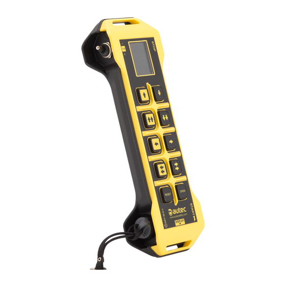
Page 13: Description Of The Transmitting Unit
Description of the Transmitting Unit Description of the Transmitting Unit Description of LK NEO 10 and LK NEO 12 Transmitting Units (Model LKN Type LA2EM) AUTEC - Air series LIULK1ES0_eng-01... - Page 14 Power keyswitch (if present) Battery housing Transmitting Unit identification plate Radio Remote Control identification plate Technical data plate START pushbutton FUNCTION pushbutton Command pushbuttons STOP pushbutton "Enabling&Stop" pushbutton DIP switches Connector for "ID internal tx memory" LIULK1ES0_eng-01 AUTEC - Air series...
- Page 15 Description of the Transmitting Unit Description of LK NEO 10 DF Transmitting Unit (Model LKN Type DA2FM) AUTEC - Air series LIULK1ES0_eng-01...
- Page 16 Power keyswitch (if present) Battery housing Transmitting Unit identification plate DISPLAY pushbutton Radio Remote Control identification plate Technical data plate START pushbutton FUNCTION pushbutton Command pushbuttons STOP pushbutton "Enabling&Stop" pushbutton DIP switches Connector for "ID internal tx memory" LIULK1ES0_eng-01 AUTEC - Air series...
-
Page 17: Technical Data
A Technical Data Sheet must always be kept together with this Manual: if you need to use the Technical Data Sheet for administrative purposes (tests, check, etc.), make a copy of it. The wiring of the Receiving Unit's outputs must always reflect the wiring indicated in the Technical Data Sheet. AUTEC - Air series LIULK1ES0_eng-01... -
Page 18: Plates
Manufacturing year, bar code and Transmitting Unit Battery housing Transmitting Unit identification number identification plate (TU ID) MODEL, TYPE and main Transmitting Technical data plate Battery housing Unit technical data, marking and possible Radio Remote Control marks LIULK1ES0_eng-01 AUTEC - Air series... -
Page 19: Plates On The Lk Neo 10, Lk Neo 12 And Lk Neo 10 Df (Model Lkn Type La2Em, Da2Fm) Transmitting Unit In A "Multi Units" Or "Multi Receiver" Radio Remote Control
Manufacturing year, bar code and Transmitting Unit Battery housing Transmitting Unit identification number identification plate (TU ID) MODEL, TYPE and main Transmitting Technical data plate Battery housing Unit technical data, marking and possible Radio Remote Control marks AUTEC - Air series LIULK1ES0_eng-01... -
Page 20: Light Signals
The meaning of red LED [A] and green LED [B] signals is described in the following tables; possible actions to carry out are given in chapter 11. The meaning of the red and green LED signals cannot be modified. LIULK1ES0_eng-01 AUTEC - Air series... - Page 21 The red LED [A] blinks slowly (one The battery has less than 1h run time. blink per second). The red LED [A] blinks fast. The battery has a 10min run time. AUTEC - Air series LIULK1ES0_eng-01...
- Page 22 30 s left before the Transmitting Unit automatically blink alternating. switches off. The green LED [B] repeats the sequence: 3 blinks and a pause, The UNPAIR procedure has been carried out. and the red LED [A] is steady on during start up. LIULK1ES0_eng-01 AUTEC - Air series...
-
Page 23: Light Signals On The Lk Neo 10 Df Transmitting Unit (Model Lkn Type Da2Fm)
The meaning of red LED [A] and green LED [B] signals is described in the following tables; possible actions to carry out are given in chapter 11. The meaning of the red and green LED signals cannot be modified. AUTEC - Air series LIULK1ES0_eng-01... - Page 24 The red LED [A] blinks slowly (one The battery has less than 1h run time. blink per second). The red LED [A] blinks fast. The battery has a 10min run time. LIULK1ES0_eng-01 AUTEC - Air series...
- Page 25 Very low power level (red bar): the battery has 10min run time from the beginning of this signal. The Unit is about to switch off (blinking red bar): the battery has 2min run time from the beginning of this signal. AUTEC - Air series LIULK1ES0_eng-01...
- Page 26 The Radio link icon [E] consists of five vertical bars. The amount of dark bars is proportional to the quality of radio link. Symbol Meaning Strong radio link signal. Medium radio link signal. No radio link. LIULK1ES0_eng-01 AUTEC - Air series...
-
Page 27: General Operating Instructions
2. rotate the power keyswitch clockwise. 8.1.4 power keyswitch removal Perform the following operations to remove the power keyswitch: 3. rotate the power keyswitch anticlockwise, 4. pull the power keyswitch to remove it from the corresponding housing. AUTEC - Air series LIULK1ES0_eng-01... -
Page 28: Start Pushbutton
It is not possible to scroll the lines if icons only are displayed. The display lighting stays on for a time set by the Machine Manufacturer. No function other than the above mentioned functions must be given to the display pushbutton when the Unit is installed. LIULK1ES0_eng-01 AUTEC - Air series... -
Page 29: Enabling&Stop" Pushbutton
To start the Radio Remote Control again and enable it to control the Machine after the "Enabling&Stop" pushbutton has activated the stop, you need to: - make sure that the working and usage conditions are safe, - start the Radio Remote Control following the procedure described in paragraph 8.11. AUTEC - Air series LIULK1ES0_eng-01... - Page 30 SO COULD DAMAGE THE UNIT, PREVENTS THE PROPER FUNCTIONING OF THE UNIT AND COULD CAUSE SERIOUS INJURY OR DEATH, AND/OR PROPERTY DAMAGE. The stop function activated by the ”Enabling&Stop” pushbutton meets the requirements up to PL=d according to the EN ISO 13849-1. LIULK1ES0_eng-01 AUTEC - Air series...
-
Page 31: Battery
General operating instructions Battery The Air series' Transmitting Units can only be powered by Autec rechargeable batteries. For any warnings and instructions regarding the battery, see "Part E" in the Instruction Manual. 8.7.1 Battery insertion Push the battery towards the contacts on the Transmitting Unit (1) and insert it inside the housing (2). - Page 32 - 3 LEDs on: maximum level. Run time indication disappears after some seconds. Commands associated to the actuators that are activated during the procedure to check the battery charge level are not sent to the Machine. LIULK1ES0_eng-01 AUTEC - Air series...
-
Page 33: Id Internal Tx Memory
When the Transmitting Unit does not have the"Key ID 0-1" (see paragraph 8.1.2), the Technical Data Sheet shows if an "ID internal tx memory" is present (DIP switch 2 is set in the ON position). AUTEC - Air series LIULK1ES0_eng-01... -
Page 34: Zero-G Sensor
- Tilt: the Zero-G sensor activates when the Transmitting Unit is tilted for more than one second by a defined angle with respect to the ground. The value of the tilting angle is set by Autec, but it is decided by the Machine Manufacturer and/or by the Installer (possible options: 45°/60°/90°). -
Page 35: Starting Up The Radio Remote Control
4. press the START pushbutton and hold it down until the green LED blinks quickly. 5. release the START pushbutton. When the green LED blinks slowly, the Radio Remote Control is active and it can send commands and activate the Machine. AUTEC - Air series LIULK1ES0_eng-01... - Page 36 Note: default PIN code set by AUTEC is: - PIN 1=START pushbutton. - PIN 2=FUNCTION pushbutton. - PIN 3=START pushbutton. Autec will set a customized PIN code only upon request by the Machine Manufacturer or the Installer. LIULK1ES0_eng-01 AUTEC - Air series...
- Page 37 6. press the START pushbutton and hold it down until the green LED blinks quickly. 7. release the START pushbutton. When the green LED blinks slowly, the Radio Remote Control is active and it can send commands and activate the Machine. AUTEC - Air series LIULK1ES0_eng-01...
-
Page 38: Command Activation
The Transmitting Unit automatically switches off when: - the battery is flat (see paragraph 8.14.1), - the Radio Remote Control is not used for a certain time (see paragraph 8.14.2). To start the Radio Remote Control, see paragraph 8.11. LIULK1ES0_eng-01 AUTEC - Air series... -
Page 39: Switching Off The Transmitting Unit
(SWITCH-OFF) to zero. Setting or removal of the automatic switch off time (SWITCH-OFF) is done by Autec and decided by the Machine Manufacturer or by the Installer, depending on the operation and functions they need on the Machine. -
Page 40: Data Feedback" Function
If the Transmitting Unit has an LED array for the "Data Feedback" function, specific Machine conditions are signalled if they are illuminated (by way of example: load limits, limit switch). The signalled conditions depend on the settings chosen by the Machine Manufacturer. LIULK1ES0_eng-01 AUTEC - Air series... -
Page 41: Back-Up Unit
"BACK-UP UNIT", so that all Units belonging to the Radio Remote Control will show the same serial number. Autec cannot be held responsible if the serial number of the Transmitting Unit to be replaced has not been marked on the "BACK-UP UNIT". -
Page 42: Instructions For The User
User by the Manufacturer of the Machine where an Autec Radio Remote Control (to which the LK NEO 10, LK NEO 12 and LK NEO 10 DF (Model LKN Type LA2EM, DA2FM) Transmitting Unit belongs) is installed. - Page 43 - keep at a safe distance from any risk situations originating from the use of the Machine where the Autec Radio Remote Control is installed; - avoid doing anything else while using the Radio Remote Control, such as, by way of example, operate other Machines and/or other devices, eat and/or drink, use communication devices (phone, radio phone, etc.), keyboards, computers, IT devices or AV equipment,...
-
Page 44: Belt And Pouch With Belt
Transmitting Unit always comes with a belt or a pouch with belt: the User must mount and use the belt and the pouch with belt as explained in the paragraphs 9.3.1 and 9.3.2. 9.3.1 Belt or harness Assembly LIULK1ES0_eng-01 AUTEC - Air series... - Page 45 Instructions for the User AUTEC - Air series LIULK1ES0_eng-01...
- Page 46 Transmitting Unit, to the User, to people and/or property. Replace the belt or harness if it is damaged or worn. LIULK1ES0_eng-01 AUTEC - Air series...
- Page 47 Instructions for the User 9.3.2 Pouch with belt Assembly AUTEC - Air series LIULK1ES0_eng-01...
- Page 48 Transmitting Unit, to the User, to people and/or property. Replace the pouch with belt if it is damaged or worn. LIULK1ES0_eng-01 AUTEC - Air series...
-
Page 49: Maintenance
(it is possible to send commands). The green LED blinks See "Malfunctions signalled by the The Receiving Unit may slowly Receiving Unit " in "Part D" of the not work correctly. (one blink per second). Manual. AUTEC - Air series LIULK1ES0_eng-01... - Page 50 The green and red LEDs The "Key ID 0-1" or the Contact the support service of the blink three times per "ID internal tx memory" is Machine Manufacturer. second during start up. damaged. LIULK1ES0_eng-01 AUTEC - Air series...
-
Page 51: Decommissioning And Disposal
Decommissioning and disposal Instructions for correct decommissioning and disposal of Radio Remote Controls are described in chapter "Decommissioning and disposal" in "Part A" of the Instruction Manual. Therefore, please refer to that part of the Manual. AUTEC - Air series LIULK1ES0_eng-01... - Page 52 Via Pomaroli, 65 - 36030 Caldogno (VI), ITALY PH: +39 0444 901000 - Fax: +39 0444 901011 info@autecsafety.com - www.autecsafety.com MADE IN ITALY...
Need help?
Do you have a question about the AIR SERIES and is the answer not in the manual?
Questions and answers