
Related Manuals for golmar SV-372S Color


Summary of Contents for golmar SV-372S Color
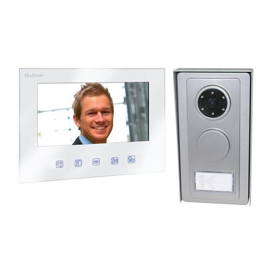
- Page 1 Video door entry system Kits 2 wires installation SV-372S Color Instructions manual...
-
Page 2: Table Of Contents
Always use 12 Vd.c. lock releases Golmar (cod. 20600149, not included in the kit). Do not switch voltage higher than 12 Vd.c. / 1A between C and NO door panel terminals. -
Page 3: System Characteristics
SYSTEM CHARACTERISTICS Video door entry system with simplified installation (2 wire bus). Two different types of installation: Power supply connected to monitor, (see installation diagram, cable and sections pages 55-56). Power supply connected into the bus, (see installation diagram, cable and sections pages 57-58). System maximum distance, (see pages 55-58). -
Page 4: Description
DOOR PANEL DESCRIPTION oor panel description PVS-222 C olour Solo abrepuertas de corriente contínua only d.c lock release CV BUS Screws of fixation of the aluminium front (x2). Call push button for 1 or 2 apartments, (see pages 45, 55 and 57). Label push button. - Page 5 DOOR PANEL INSTALLATION oor panel positioning. 1850 1650 1450 The upper part of the door panel should be placed at 1,65m. The door panel has been designed to be placed under most of the environmental conditions. However it´s recommended to take additional cautions, like the use of the supplied rainproof cover or the installation under a covered place.
- Page 6 DOOR PANEL INSTALLATION lace the door panel. Face the door panel to the wall by placing the top at 1,65m. height and insert the installation wires through the cables entry. Drill two holes of 6mm. diameter and insert the wallplugs. Fix the door panel with especified screws.
-
Page 7: Final Adjustements
DOOR PANEL INSTALLATION inal adjustments. If after starting the system it's considered that the audio volume isn't correct, proceed with the necessary adjustments as shown on the picture. ush button label. To customize the push button label, insert a flat screwdriver to accede to the label, remove the push button front cover, see picture A &... -
Page 8: Lock Release Installation
The FA-372 power supply uses 3 units over DIN guide. This device has been exclusively designed to be used on Golmar Kit video SV-372S Colour. Golmar will not be responsible of the possible damages caused for an improper use or when used for other purposes than the specified. -
Page 9: Description
MONITOR DESCRIPTION escription 372S colour monitor. OUT 1 Colour screen 7". function push buttons. Led indicator of function push button pressed. Microphone. Speaker. Switch End of Line. Attachment holes for bracket installation. Installation terminals: : Positive ( FA-372 power supply) : Negative ( FA-372 power supply) : Input communication Bus (see installation diagrams page 55 and 57 . - Page 10 MONITOR DESCRIPTION unction push buttons. Push button to stablish / finish communication or intercom function (only available on systems with 2 or more monitors in the same apartment, for description and connection see page 52, 55 & 57). In configuration menu mode: To scroll up through the menu or to increase the value of the selected option, (see page 53).
- Page 11 MONITOR INSTALLATION emove the bracket installation. Unscrew the monitor bottom screws. OUT 1 Remove the bracket installation of the monitor. OUT 1 ix the bracket installation to the wall. Avoid to place the monitor near to heating sources, in dusty locations or smoky environments. The bracket can be fixed using an electrical emmbeding box or directly on the wall.
- Page 12 MONITOR INSTALLATION onitor wiring. Connect the installation wires to the terminal connector, according to the installation diagrams. ix the monitor. Place the monitor align attaching holes of the monitor with the attachment hooks of the bracket installation. With help of an screwdriver, fix the monitor with especified screws, as shown on the picture.
-
Page 13: Intercom Function
MONITOR INSTALLATION ntercom function. 372S colour monitor, incorporate as standard the intercom function between two monitors of the same apartment in systems with two or more monitors. To enable this function it will be necessary that one monitor has been configurated as master and slave the rest of monitors, (see page 54). -
Page 14: Monitor Adjustments
MONITOR ADJUSTMENTS/PROGRAMMING onitor adjustments and programming. the configuration menu of the monitor allows changing the following options: -Selecting the Video option: Brightness, Contrast and Colour. -Selecting the Audio option: To select melody, melody volume and voice volume. -Selecting the ID option: To select house and to select room (Master/Slave). the following buttons on the front panel of the monitor allow to perform the next functions: Enter / exit the configuration menu mode. - Page 15 MONITOR ADJUSTMENTS/PROGRAMMING Coming from previous page To select a melody volume for call monitor, choose the "Audio" option with help of the scroll buttons and select this option by pressing the button ; the following SELECT MELODY VIDEO menu will be displayed. Then choose the "Melody AUDIO MELODY VOLUME VOICE VOLUME...
-
Page 16: Installation Diagram
INSTALLATION DIAGRAM onnection to 1 apartment (power supply connected to monitor), Bus without polarity. Apartment 1 3rd Slave Monitor 2nd Slave Monitor 1st Slave Monitor Master Monitor 372S colour 372S colour 372S colour 372S colour FA-372 End of Line End of Line End of Line End of Line 230Vac... -
Page 17: Sections Chart
INSTALLATION DIAGRAM ections chart. Terminal (4) Cable (twisted/ multipaired) (1)BUS,BUS CV, CV 25m. AWG24: 2 wire (0,20mm²) 50m. AWG19: 2 wire (0,65mm²) AWG19: 2x2 wire (0,65x2= 1,30mm²) 100m. 50m. CAT6 AWG23: 2 wire (0,26mm²) CAT6 AWG23: 2x2 wire 100m. (0,26x2= 0,52mm²) 100m. - Page 18 INSTALLATION DIAGRAM onnection to 1 apartment (power supply connected into the bus), Bus with polarity. Apartment 1 3rd Slave Monitor 2nd Slave Monitor 1st Slave Monitor Master Monitor 372S colour 372S colour 372S colour 372S colour FA-372 End of line End of line End of line End of line...
- Page 19 INSTALLATION DIAGRAM ections chart. Terminal (5) Cable (twisted/ multipaired) (1)BUS,BUS (2)BUS,BUS (3)BUS,BUS CV, CV 25m. 25m. -------- AWG24: 2 wire (0,20mm²) 50m. 50m. -------- AWG19: 2 wire (0,65mm²) 100m. 50m. -------- AWG19: 2x2 wire (0,65x2= 1,30mm²) 50m. 100m. -------- 40m. 25m.
-
Page 20: Troubleshooting Hints
INSTALLATION DIAGRAM onnection of an auxiliary device or control for gate automation. Auxiliary device Control for gate automation PVS-222 PVS-222 colour colour TF-104 CV CV CV CV 230Vac 12Vac -For higher consumption than 12Vd.c. / 1A between 'C' and 'NO', contact our technical support department. -' ' C and NO c ' ontact free auxiliary... -
Page 21: Notes
NOTAS/NOTES... - Page 22 NOTAS/NOTES...
- Page 23 NOTAS/NOTES...
- Page 24 A fordításból, illetve a nyomdai kivitelezésből származó hibákért felelősséget nem vállalunk. A leírás és a termék változtatásának jogát a forgalmazó és a gyártó fenntartja. Golmar se reserva el derecho a cualquier modificación sin previo aviso. Golmar se réserve le droit de toute modification sans préavis.
Need help?
Do you have a question about the SV-372S Color and is the answer not in the manual?
Questions and answers