
Subscribe to Our Youtube Channel
Related Manuals for golmar 50124319


Summary of Contents for golmar 50124319
- Page 1 Cód. 50124319 Audio and Video door entry system digital installation with coded panel Stadio Plus Instructions manual T3403ML rev.0112...
-
Page 2: Table Of Contents
Each time the power supply is restarted, or after a modification, the system will remain blocked during 30 seconds. Always use RG-59 B/U MIL C-17 or RG-11 coaxial cables, (see page 110). Never use coaxial antenna cable. In installations no longers than 100m., Golmar RAP-5130 cable can be used. -
Page 3: Safety Precautions
SAFETY PRECAUTIONS Install or modify the equipment without the power connected. The installation and handling of these equipments must be performed by authorised personnel. The entire installation must be at least 40 cm. away from any other installation. With power supply: wDo not use excessive force when tightening the connector screws. -
Page 4: System Characteristics
SYSTEM CHARACTERISTICS Microprocessed systems with bus installation (no call wires): Audio system with 4 common wires installation. Video system with 3 common wires plus coaxial cable. Video system with 4 common wires plus twisted pair cable. Unlimited number of door panels (access) being not necessary the use of switching units. Up to 1000 monitors/telephones per installation or backbone. -
Page 5: System Operation
SYSTEM OPERATION One building systems. To make a call, the visitor should key-in the three digits code corresponding to the apartment he wishes to contact: the door panel display will show the sequence keyed-in. Once the code has been introduced, press bell key to confirm the call: acoustic tones will be heard confirming the call is in progress and the door panel display will show the message calling. -
Page 6: Door Panel Installation
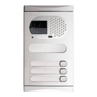
DOOR PANEL INSTALLATION mbedding box positioning. 1850 1650 1450 The upper part of the door panel should be placed at 1,65m. height roughly. The hole dimensions will depend on the number of door panel modules. Modules CE630 Model CE610 CE620 125 mm. -
Page 7: Embedding Box Positioning
DOOR PANEL INSTALLATION lace the embedding box. Pass the wiring through the hole made in the bottom part of the embedding box. Level and flush the embedding box. Once the embedding box is placed, remove the protective labels from the attaching door panel holes. ssembly the door panel modules. -
Page 8: Door Panel Fixing And Wiring
DOOR PANEL INSTALLATION ssembly the sound module. Insert the sound module in the grille module. For a proper assembly, align the light push button and the microphone rubber of the sound module with its corresponding holes in the grille module. old the door panel on the embedding box. - Page 9 DOOR PANEL INSTALLATION escription of the configuration jumpers. The JP1, JP2, JP3 and JP4 configuration jumpers are placed on the left side of the terminal connector. Jumper JP1 loads the installation with a communications resistor. For a proper system operation, activate this resistor only in the closest door panel to the backbone installation or in the general entrance door panel (if exists).
-
Page 10: Door Panel Settings
DOOR PANEL INSTALLATION ptional. EL560 module for video installations with twisted pair cable. Plug the EL560 module in the CN6 connector. The CN4 connector is accessible by unbolting the four screws of the pcb protection cover. NOTE: on this type of installations the EL562 module must be plugged in all the monitors. -
Page 11: Final Adjustments
DOOR PANEL INSTALLATION nformative module lamps wiring. Once the informative labels are placed, wire the lamps from different modules and connect them to terminals L1 and L2 of the sound module. inal adjustments. If after starting the system it's considered that the audio volume isn't correct, proceed with the necessary adjustments as shown. -
Page 12: Door Panel Programming
90 seconds with no operation. O.K. ANCEL To enter into the main programming menu, golmar press key symbol and enter 16:30 the installer PIN code (factory default: 1315) or the user PIN code (factory default: 1111). - Page 13 DOOR PANEL PROGRAMMING Coming from previous page onfiguration menu. To enter into configuration menu, follow configuration the steps described on the previous page O.K. and press when the display shows the message CONFIGURAtION Allows to choose the language of the displayed english messages and the programming menues.
- Page 14 DOOR PANEL PROGRAMMING Coming from previous page onfiguration menu. If the option YES is selected, the calls made call to exchange on the door panel will be transferred to the porter's exchange (if exists) in a first attempt. To enable this function, the porter's exchange must enable its capture panel function.
- Page 15 Coming from previous page onfiguration menu. The door panel display shows this message display mESsAgE when the system is on stand-by position. golmar Use this text to show i.e. the building name or address. To change this message press and proceed O.K.
- Page 16 DOOR PANEL PROGRAMMING Coming from previous page onfiguration menu. Allows to set the lock release activation time. door open time Modify this value when the panel is placed far from the door. The value is shown in seconds and the factory default value is 3 seconds.
- Page 17 DOOR PANEL PROGRAMMING Coming from previous page ccess control menu. To enter into access control menu, follow access control the steps described on page 119 and O.K. and press when the display shows the message access cONtrOl Allows to enable or disable the access control access control feature (lock release activation by entering a PIN code).
- Page 18 DOOR PANEL PROGRAMMING Coming from previous page ccess control menu. Defines the starting time from which code on it's possible to activate the lock release 07:15 by entering the third code. To set this time press : the display will show the message .
- Page 19 DOOR PANEL PROGRAMMING Coming from previous page epertory menu. To enter into repertory menu, follow repertory the steps described on page 119 O.K. and press when the display shows the message repertory Allows to enter a new entry in the last repertory repertory:new position.
- Page 20 DOOR PANEL PROGRAMMING Coming from previous page epertory menu. Allows to insert a new entry in a specific repertory repertory:insert position. This function allows to keep the repertory sorted. Press : the display will show the first repertory position: in case of no existing entries the O.K.
-
Page 21: Programming Menues
DOOR PANEL PROGRAMMING Coming from previous page epertory menu. It is possible to transfer the repertory content repertory:t to other panel or porter's exchange in the same installation. Before to start with the transmission, the receiving equipment must be ready for reception (see next menu). O.K. -
Page 22: Repertory Text Writing
DOOR PANEL PROGRAMMING ext edit. To introduce or edit text during programming, use the keypad as described. The maximum number of characters in one text line is 16. Use the numeric keys to introduce text: press several times the corresponding key till the desired character appears on the display, according with the enclosed characters table. -
Page 23: Power Supply Installation
POWER SUPPLY INSTALLATION nstalling the FA-PLUS and FA-PLUS/C power supplies. Install the power supply in a dry and protected place without risk of drip or water projections. To avoid an electrical shock, neither remove the primary protection cover nor handle the connected wire in the terminals. -
Page 24: Description
MONITOR DESCRIPTION escription of the Platea/Tekna Plus and Uno monitors. REF. PLATEA UNO COD. 11784022 VERSIÓN Nº SERIE X.XX 00000000000 INTER MASTER SLAVE CODIGO / CODE ATENCIÓN Alta tensión. No abrir la tapa. ESCALERA PISO PUERTA Stair Floor Door Manipular sólo por personal del servicio técnico. -
Page 25: Function Push Buttons
MONITOR DESCRIPTION unction push buttons. In Platea/Tekna Plus:On-Off push button. After any monitor reset and during the next 45 seconds, all the monitor functions will be disabled, with the exception of call reception. In Platea/Tekna Uno: On-Off light indicator. If the handset is on the craddle allows the activation of an optional second camera (*).If not, allows to make an intercom call or to activate the second camera (*). -
Page 26: El562 Module
MONITOR ADJUSTMENTS L562 module for video installations with twisted pair cable. In Platea/Tekna Plus: Locate the CN4 connector, that's placed in the monitor base. Remove the existing jumper and plug the EL562 module. In Platea/Tekna Uno: Locate the CN2 connector, that's placed in the monitor base. -
Page 27: Monitor Connector Description
MONITOR CONNECTOR DESCRIPTION escription of the RCPL-Plus / RCPL-Uno and RCTK-Plus / RCTK monitor connector. 50mm. 50mm. Malla Shield Malla Shield Presionar para abrir. Press to open. Colocar la parte superior de la regleta a 1,60m. del suelo. Place the top part of the monitor connector at 1,60m. from the floor. 11758882 CODE LOTE... -
Page 28: Monitor Installation
MONITOR INSTALLATION ix the monitor connector to the wall. Avoid to place the monitor near to heating sources, in dusty locations or smoky environments. To install the monitor directly over the wall, drill two holes of Ø6mm. and use the supplied screws. The upper part of the monitor connector must be placed at 1,60m. - Page 29 If this door panel is installed on an internal building of a residential complex or on a single building, program the monitors as follows: To enter the door panel into program mode, press golmar key symbol and enter the installer PIN code 13:15 (factory default: 1315), as described on page 119.
-
Page 30: Programming Monitors
MONITORS PROGRAMMING rogramming the monitors. For Platea/Tekna Uno monitors: Turn off the monitor to be set, by pressing the door opener button during 1 second. Once it has been turned off, press the autoswitch-on button. Keep the autoswitch-on button pressed and without releasing it, press the door opener button. - Page 31 T-740 PLUS TELEPHONE DESCRIPTION escription of the T-740 Plus telephone Telephone handset Speaker grille Microphone hole Subjection hole Telephone cord connectors Door release push button Hook switch Auxiliary function push button Volume control erminal connector description. +, - : Positive, ground. Audio, digital communication.
-
Page 32: Description
T-740 PLUS TELEPHONE DESCRIPTION unction push buttons If the handset is on the craddle sends a panic call to the porter's exchanges that have enabled the reception of this type of call. If not, allows to call to the master porter's exchange. During call reception and communication progresses allows the lock release activation. -
Page 33: Plus Telephone
T-740 PLUS TELEPHONE DESCRIPTION ix the telephone to the wall It is necessary to open the telephone for wiring and fixing purposes To open the telephone, insert a plain screwdriver into the slots and gently lever as shown in the drawing Avoid placing the telephone near sources of heat, in dusty locations or smoky environments The telephone can be fixed using an electrical embedding box or directly on the... -
Page 34: Description
T-740 UNO TELEPHONE DESCRIPTION escription of the T-740 Uno telephones. Telephone handset. Speaker grille. Microphone hole. Subjection hole. Telephone cord connectors. Function push buttons. Hook switch. unction push button. If the handset is off the hook, allows to call to the master porter's exchange. -
Page 35: Telephone Installation
T-740 UNO TELEPHONE DESCRIPTION ix the telephone. It will be necessary to open the telephone for wiring and fixing purposes. To open the telephone insert a plain screwdriver into the slots and rotate it as shown. Avoid to place the telephone near to heating sources, in dusty locations or smoky environments. - Page 36 If this door panel is installed on an internal building of a residential complex or on a single building, program the telephones as follows: To enter the door panel into program mode, press key golmar symbol and enter the installer PIN code (factory 13:15 default: 1315), as described on page 119.
-
Page 37: Programming Telephones
TELEPHONES PROGRAMMING rogramming the telephones. Only for T-740 Uno telephones: Press the door release push button and with this button pressed, pick up the handset. To show that the system is ready for programming, the panel and telephone handset will reproduce a sound (LCD will display the message . -
Page 38: Installation Diagrams
INSTALLATION DIAGRAMS Take off JP1 jumper of all the distributors except in the last one. Platea Plus/ Platea Plus/ Tekna Plus D4L-PLUS Tekna Plus Malla Malla CTin Platea Plus/ Platea Uno/ Tekna Plus Tekna Uno D4L-PLUS Malla Malla CTin M =Master. Access door panel S =Slave. - Page 39 ONE OR SEVERAL ACCESSES DOORS ideo installation with coaxial cable and Plus/Uno monitors. The installation diagram shows the connection of a video system with one or several door panels for the same building. If the system has one door panel only, override the wiring to the second door panel. If the system has more than one door panel, wire the second panel as shown on the diagram.
- Page 40 INSTALLATION DIAGRAMS Platea Plus/ Platea Plus/ Tekna Plus Tekna Plus EL562 EL562 Take off JP1 jumper of all the distributors except in the last one. D6L-Plus/2H SALIDA ENTRADA Platea Uno/ Platea Uno/ Tekna Uno Tekna Uno EL562 EL562 D6L-Plus/2H SALIDA ENTRADA M =Master.
- Page 41 ONE OR SEVERAL ACCESSES DOORS ideo installation without coaxial cable and Plus/Uno monitors. The installation diagram shows the connection of a video system with one or several door panels for the same building. If the system has one door panel only, override the wiring to the second door panel. If the system has more than one door panel, wire the second panel as shown on the diagram.
- Page 42 INSTALLATION DIAGRAMS T-740 Plus T-740 Plus T-740 Plus T-740 Uno M =Master. Access door panel S =Slave. Place this power supply as closest as possible to the first telephone. FA-Plus/C or FA-Plus Malla out+ out- 680W Main...
-
Page 43: Video Installation With Coaxial .145 To 146 Video Installation W/O Coaxial .147 To 148 Audio Installation
ONE OR SEVERAL ACCESSES DOORS udio installation with Plus/Uno telephones. The installation diagram shows the connection of an audio system with one or several door panels for the same building. If the system has one door panel only, override the wiring to the second door panel. If the system has more than one door panel, wire the second panel as shown on the diagram. - Page 44 INSTALLATION DIAGRAMS BACKBONE 1 Inner door panel To the monitors EL500 mode FA-Plus or FA-Plus/C Malla out+ out- Lock release Main D4L-PLUS CTin General door panel BACKBONE 0 M =Master. S =Slave. FA-Plus/C rev.938072 230 110 0 Malla out+ out- 12Vdc Main...
- Page 45 GENERAL DOOR PANEL BACKBONE 2 Inner door panel To the monitors EL500 mode FA-Plus or FA-Plus/C Malla out+ out- Lock release Main D4L-PLUS CTin General door panel BACKBONE 0 FA-Plus/C rev.938072 230 110 0 Malla out+ out- 12Vdc Main...
- Page 46 INSTALLATION DIAGRAMS BACKBONE 126 Inner door panel To the monitors EL500 mode FA-Plus or FA-Plus/C Malla out+ out- Lock release Main D4L-PLUS CTin ideo installation with general entrance door panel for residential complexes. IMPORTANT NOTES: To wire and configure the system properly, use this instruction manual and the ones enclosed in the internal building door panels.
- Page 47 GENERAL DOOR PANEL Example of riser with digital repeater BACKBONE 127 Inner door panel To the monitors EL500 mode FA-Plus or FA-Plus/C Malla out+ out- Lock release Main UNO SYSTEM Vout BUS 2 RD-PLUS/UNO SE BUS 1 Vout D1 Vin PLUS SYSTEM ideo installation with general entrance door panel for residential complexes.
-
Page 48: General Entrance Installation .151 To 154 Connection Of An A.c. Lock Release
INSTALLATION DIAGRAMS onnexion of an a.c. lock release. As it is described on page 130, the lock releases to be connected to the door panel must be d.c. type. If an a.c. lock release has been installed before, use a SAR-12/24 relay unit and a TF-104 transformer, and connect them to the lock release as it is shown on the enclosed diagram. - Page 49 OPTIONAL CONNECTIONS xternal lock release activation. The lock release can be activated at any moment by using an external push button, that must be connected between 'CV ' and ' ' terminals of the – – keypad module. This function will allow to exit from the building being not necessary the use of a key.
- Page 50 OPTIONAL CONNECTIONS ntercom function. Platea Plus / Tekna Plus monitor and (*) T-740Plus telephones have intercom facility between two units of the same apartment . To enable this function check the following conditions: - One of the units has been configurated as master and the other unit as slave with intercom, as described on pages 136 and 143.
- Page 51 OPTIONAL CONNECTIONS ctivation of a second camera. The use of a SAR-12/24 relay will be required to activate a second camera and an internal modification on the monitor shall be done, as it's described on page 132. This facility disables the intercom function.
- Page 52 OPTIONAL CONNECTIONS uxiliary devices activation with T-740 Plus telephone. First t T-740 Plus telephone must be configured with SW1 dip switch in "PA" output mode function (see page 139). To activate auxiliary devices the use of a SAR-12/24 relay unit will be required. If this device is shared for all the T-740 Plus telephones, link their PA terminal and use just one relay unit.
-
Page 53: Optional Connections
OPTIONAL CONNECTIONS onnection of a repeater RD-Plus/Uno SE. If there's one or more Uno monitors or telephones in the installation, if the distance between the door panel and the last monitor or telephone exceeds 200 metres, or if the building has more than 200 monitors or telephones, a digital repeater RD-Plus/Uno SE should be installed. -
Page 54: Troubleshooting Hints
TROUBLESHOOTING HINTS An easy way to check that the system is working properly is to disconnect the wiring from the door panel and to check the monitor directly connected to the door panel terminal connector. No shortcircuit will damage the connected units, with the exception of a shortcircuit between CTO and ' ' monitor or distributor terminals. -
Page 55: Notes
NOTAS / NOTES... - Page 56 Golmar se reserva el derecho a cualquier modificación sin previo aviso. Golmar se réserve le droit de toute modification sans préavis. Golmar reserves the right to make any modifications without prior notice.
Need help?
Do you have a question about the 50124319 and is the answer not in the manual?
Questions and answers