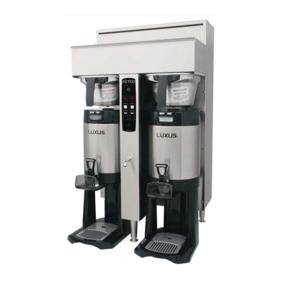
Fetco CBS-2041e User Manual
Fetco cbs-2041e: users guide
Hide thumbs
Also See for CBS-2041e:
- User manual (22 pages) ,
- Technical bulletin (1 page) ,
- Programming instructions (1 page)
Table of Contents
Advertisement
www.fetco.com
Contact Information ................................................ 2
Description & Features ........................................... 2
Specifications.......................................................... 2
Requirements...................................................... 2
Dimensions & Utility Connections........................... 4
Installation............................................................... 5
Operating Instructions ............................................ 8
Programming .......................................................... 9
Batch Settings ..................................................... 9
FETCO®, LUXUS®, and EXTRACTOR™ are trademarks or trade names of Food Equipment Technologies Company.
© 2003 Food Equipment Technologies Company
Models:
CBS-2041
CBS-2042
NOTICE TO INSTALLER: This book contains important
programming instructions that will be needed by the
customer. Please leave it with the manager or
responsible person at the machine location.
Table of Contents
User's Guide
Temperature Settings ....................................... 10
Advanced Settings and Diagnostics ................. 10
Relay Test ......................................................... 11
Error Codes .......................................................... 12
Service.................................................................. 13
Cleaning & Maintenance ...................................... 13
Wiring Diagrams ................................................... 14
Parts ..................................................................... 16
Part # P018
June 13, 2003
Advertisement
Table of Contents

Related Manuals for Fetco CBS-2041e


Summary of Contents for Fetco CBS-2041e
-
Page 1: Table Of Contents
Dimensions & Utility Connections... 4 Installation... 5 Operating Instructions ... 8 Programming ... 9 Batch Settings ... 9 FETCO®, LUXUS®, and EXTRACTOR™ are trademarks or trade names of Food Equipment Technologies Company. © 2003 Food Equipment Technologies Company User’s Guide Models: CBS-2041 CBS-2042 customer. -
Page 2: Contact Information
Drip delay (The time between the end of the brew cycle and the unlocking of the brew basket.) Magnetic brew basket sensor Brew basket safety locks Brew temperature protection Specifications Electrical: See electrical configuration chart. Coffee Filters: 13” X 5 ” FETCO Product # F002... -
Page 3: Electrical Configuration And Brewing Efficiency
Electrical Configuration and Brewing Efficiency US & Canada CBS-2041 Electrical Heater Config. Code Configuration E41046 1 X 1.5 KW Can be connected 2 X 1.5 KW to 120 VAC or 120/208-240 VAC E41036 1 X 1.7 KW Can be connected 2 X 1.7 KW to 120 VAC or 120/208-240 VAC... -
Page 4: Dimensions & Utility Connections
Dimensions & Utility Connections CBS-2041 CBS-2042... -
Page 5: Installation
Here are the key points to consider before installation: Electrical: All FETCO brewers require NEUTRAL. Ground is not an acceptable substitute. Installation without neutral may cause damage to the electronic components. The electrical diagram is located on the inside of the lower cover. - Page 6 Electrical Connection – US & Canada 1. Verify that the actual voltage at the electrical service connection is compatible with the specifications on the brewer’s serial number label. Make sure the electrical service includes neutral. 2. The temperature and water tank fill level are pre-set at the factory. There is no need to turn off the heaters during the installation process.
- Page 7 Final Setup 1. Turn on the incoming water supply line and inspect both inside and outside of the brewer for leaks in all fittings and tubes 2. Turn on the incoming power. 3. Press the brewer’s main power switch, which is hidden behind the front leg of the brewer.
-
Page 8: Operating Instructions
Control Panel Functions Only switches that are active are illuminated. Switches that are inactive or disabled are invisible. Main Power Switch Controls all power to brewer Indicator lamp at top of panel. Control Panel On/Off Switch Affects only control panel. Does not disconnect main power. -
Page 9: Programming
Batch Settings Turn the brewer off by pressing the main power switch. Press the main power switch again to turn the unit on. Quickly hold the STOP button for 3 seconds. The display will show the software version for 3 seconds. Example: Batches are numbered 1 –... -
Page 10: Temperature Settings
Temperature Settings Parameter Name Water Temp. (°F) Hot Water Service Brew at Set Temperature Parameter Name Enter Advanced Settings & Diagnostics Important! To save your changes, press Advanced Settings and Diagnostics Address Description Water Level in Tank Water Resistance Brew Basket Sensor State (left / right) Power Relay State... -
Page 11: Relay Test
Address Description Left Brew Valve Flow Rate Right Brew Valve Flow Rate Left Bypass Valve Flow Rate Right Bypass Valve Flow Rate Keypad Test Relay Test Press to save the settings and exit Diagnostic mode. Press again to exit Programming mode and return to Operating mode. Relay Test Tests the individual relays which control various components. -
Page 12: Error Codes
Code Description Possible Cause Internal Error Control board System had to failure. reload default settings. Power Failure Relay on control Power state does board has failed. not match feedback loop state. Shorted Probe failure. temperature probe. Open temperature Bad probe probe. -
Page 13: Service
45 seconds. Utilize only qualified beverage equipment service technicians for service. A Service Company Directory may be found on our web site, http://www.fetco.com. Companies listed as “Extractor Authorized” stock parts for these models. When changing the control board, check the software version on the chip. Example- V2.11. If the chip on the replacement board has an older software version than the board being replaced, carefully remove the chip from the old board and place it in the new board. -
Page 14: Wiring Diagrams
Wiring Diagrams CBS-2041... - Page 15 CBS-2042...
-
Page 16: Parts
Main assembly and tank assembly drawings were not available at time of publication. Figure 3 – Spray Housing Assembly – CBS-2041 & CBS-2042 ITEM # PART NO DESCRIPTION 82112 #8 X 3/4'' PAN HD. PHIL. T.S. 18-8 S.S. SCREW 57047 COIL ASSY. REPAIR KIT, DSV-11, 120 VAC 57071 COIL ASSY. - Page 17 Figure 4 – Brew Basket Assembly, 13” X 5”, Part # 101175 ITEM PART # DESCRIPTION 09022 WIRE INSERT, 13” X 5 23117 BREW BASKET HANDLE, BLACK 46011 WARNING LABEL 82096 HANDLE SCREW 57082 MAGNET PAPER FILTERS, 13” X 5” F002 SHOWN 500 PER CASE...
Need help?
Do you have a question about the CBS-2041e and is the answer not in the manual?
Questions and answers