Table of Contents
Advertisement
Quick Links
Advertisement
Table of Contents

Related Manuals for Supero A+ SERVER 1022G-NTF


Summary of Contents for Supero A+ SERVER 1022G-NTF
- Page 1 ® UPER A+ SERVER 1022G-NTF USER’S MANUAL Revision 1.0c...
- Page 2 The information in this User’s Manual has been carefully reviewed and is believed to be accurate. The vendor assumes no responsibility for any inaccuracies that may be contained in this document, makes no commitment to update or to keep current the information in this manual, or to notify any person or organization of the updates.
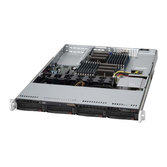
- Page 3 About This Manual This manual is written for professional system integrators and PC technicians. It provides information for the installation and use of the A+ SERVER 1022G-NTF. In- stallation and maintenance should be performed by experienced technicians only. The A+ SERVER 1022G-NTF is a 1U rackmount server based on the SC815TQ- 563UBP server chassis and the Super H8DGU-F serverboard.
- Page 4 A+ SERVER 1022G-NTF User's Manual Chapter 6: Advanced Chassis Setup Refer to Chapter 6 for detailed information on the SC815TQ-563UBP chassis. You should follow the procedures given in this chapter when installing, removing or reconfi guring Serial ATA or peripheral drives and when replacing system power supply units and cooling fans.
- Page 5 Preface Notes...
-
Page 6: Table Of Contents
A+ SERVER 1022G-NTF User's Manual Table of Contents Chapter 1 Introduction Overview ......................1-1 Serverboard Features ..................1-2 Processors ...................... 1-2 Memory ......................1-2 UIO ........................1-2 Serial ATA ....................... 1-2 Onboard Controllers/Ports ................1-2 Graphics Controller ..................1-3 Other Features ....................1-3 Server Chassis Features ................ - Page 7 Table of Contents Installing the Server into the Rack ..............2-6 Installing the Server into a Telco Rack ............2-7 Checking the Serverboard Setup ..............2-8 Checking the Drive Bay Setup ................ 2-9 Chapter 3 System Interface Overview ......................3-1 Control Panel Buttons ..................
- Page 8 A+ SERVER 1022G-NTF User's Manual Adding PCI Cards ..................5-10 PCI Expansion Slots ................5-10 Serverboard Details ..................5-11 H8DGU(-F) Quick Reference ................ 5-12 Connector Defi nitions ................... 5-13 Power Connectors ................... 5-13 PW_ON Connector ................... 5-13 Reset Connector ..................5-13 Overheat/Fan Fail LED (OH)..............
- Page 9 Using the Adaptec RAID Utility ..............5-25 Installing the RAID Driver During OS Installation ......... 5-25 5-13 Installing Drivers .................... 5-26 Supero Doctor III ................... 5-27 Chapter 6 Advanced Chassis Setup Static-Sensitive Devices .................. 6-1 Precautions ..................... 6-1 Control Panel ....................6-2 System Fans ....................
- Page 10 A+ SERVER 1022G-NTF User's Manual Appendix A BIOS Error Beep Codes Appendix B Installing Windows Installing Windows to a RAID System ............B-1 Installing Windows to a Non-RAID System ............ B-2 Appendix C System Specifi cations...
-
Page 11: Chapter 1 Introduction
Chapter 1 Introduction Overview The A+ SERVER 1022G-NTF is a high-end server comprised of two main subsystems: the SC815TQ-563UBP 1U server chassis and the H8DGU-F dual processor serverboard. Please refer to our web site for information on operating systems that have been certifi ed for use with the system (www.supermicro.com). -
Page 12: Serverboard Features
VER 1022G-NTF User's Manual Serverboard Features At the heart of the A+ SERVER 1022G-NTF lies the H8DGU-F, a dual processor serverboard based on the AMD SR5670/SP5100 chipset. Below are the main features of the H8DGU-F. (See Figure 1-1 for a block diagram of the chipset). -
Page 13: Graphics Controller
Chapter 1: Introduction Graphics Controller The H8DGU-F features an integrated Matrox G200eW graphics chip, which includes 16 MB of DDR2 memory. Other Features Other onboard features that promote system health include onboard voltage monitors, auto-switching voltage regulators, chassis and CPU overheat sensors, virus protection and BIOS rescue. -
Page 14: I/O Backplane
+ SE VER 1022G-NTF User's Manual I/O Backplane The SC815TQ-563UBP is an extended ATX form factor chassis that is designed to be used in a 1U rackmount confi guration. Ports on the I/O backplane include one COM port, a VGA port, two USB 2.0 ports, PS/2 mouse and keyboard ports, a dedicated LAN port for IPMI and two gigabit Ethernet ports. - Page 15 Chapter 1: Introduction Figure 1-1. AMD SR5670/SP5100 Chipset: System Block Diagram Note: This is a general block diagram. Please see Chapter 5 for details. DIMM A1 HT3 Link DIMM A1 DIMM A0 8x8-3.2GT/s DIMM A0 DIMM B1 DIMM B1 DIMM B0 HT3 Link Socket G34 DIMM B0...
-
Page 16: Contacting Supermicro
+ SE VER 1022G-NTF User's Manual Contacting Supermicro Headquarters Address: Super Micro Computer, Inc. 980 Rock Ave. San Jose, CA 95131 U.S.A. Tel: +1 (408) 503-8000 Fax: +1 (408) 503-8008 Email: marketing@supermicro.com (General Information) support@supermicro.com (Technical Support) Web Site: www.supermicro.com Europe Address: Super Micro Computer B.V. -
Page 17: Chapter 2 Server Installation
Unpacking the System You should inspect the box the A+ SERVER 1022G-NTF was shipped in and note if it was damaged in any way. If the server itself shows damage you should fi le a damage claim with the carrier who delivered it. -
Page 18: Warnings And Precautions
+ SE VER 1022G-NTF User's Manual Choosing a Setup Location • Leave enough clearance in front of the rack to enable you to open the front door completely (~25 inches) and approximately 30 inches of clearance in the back of the rack to allow for suffi cient airfl ow and ease in servicing.This product is for installation only in a Restricted Access Location (dedicated equipment rooms, service closets and the like). -
Page 19: Rack Mounting Considerations
Chapter 2: Server Installation • Allow the hot plug SATA drives and power supply modules to cool before touching them. • Always keep the rack's front door and all panels and components on the serv- ers closed when not servicing to maintain proper cooling. Rack Mounting Considerations Ambient Operating Temperature If installed in a closed or multi-unit rack assembly, the ambient operating... -
Page 20: Installing The System Into A Rack
+ SE VER 1022G-NTF User's Manual Installing the System into a Rack This section provides information on installing the 1022G-NTF into a rack unit with the rack rails provided. If the system has already been mounted into a rack, you can skip ahead to Sections 2-5 and 2-6. -
Page 21: Installing The Outer Rails
Chapter 2: Server Installation Installing the Outer Rails Begin by measuring the distance from the front rail to the rear rail of the rack. Attach a short bracket to the front side of the right outer rail and a long bracket to the rear side of the right outer rail. -
Page 22: Installing The Server Into The Rack
+ SE VER 1022G-NTF User's Manual Installing the Server into the Rack You should now have rails attached to both the chassis and the rack unit. The next step is to install the server into the rack. Do this by lining up the rear of the chassis rails with the front of the rack rails. -
Page 23: Installing The Server Into A Telco Rack
Chapter 2: Server Installation Installing the Server into a Telco Rack To install the 1022G-NTF into a Telco type rack, use two L-shaped brackets on either side of the chassis (four total). First, determine how far follow the server will extend out the front of the rack. -
Page 24: Checking The Serverboard Setup
+ SE VER 1022G-NTF User's Manual Checking the Serverboard Setup After you install the 1022G-NTF in the rack, you will need to open the top cover to make sure the serverboard is properly installed and all the connections have been made. Accessing the Inside of the System First, grasp the two handles on either side and pull the system straight out until it locks (you will hear a "click"). -
Page 25: Checking The Drive Bay Setup
Chapter 2: Server Installation Figure 2-5. Accessing the Inside of the System Checking the Drive Bay Setup Next, you should check to make sure the peripheral drives and the SATA drives and SATA backplane have been properly installed and all connections have been made. Checking the Drives All drives are accessable from the front of the server. - Page 26 + SE VER 1022G-NTF User's Manual Checking the Airfl ow Airfl ow is provided by four sets of 4-cm fans (each set of fans consists of two fans that are mounted back to back). The system component layout was carefully designed to direct suffi cient cooling airfl ow to the components that generate the most heat.
-
Page 27: Chapter 3 System Interface
Chapter 3: System Interface Chapter 3 System Interface Overview There are several LEDs on the control panel as well as others on the SATA drive carriers to keep you constantly informed of the overall status of the system as well as the activity and health of specifi... -
Page 28: Power
+ SE VER 1022G-NTF User's Manual Power The main power button is used to apply or remove power from the power supply to the server system. Turning off system power with this button removes the main power but keeps standby power supplied to the system. Control Panel LEDs The control panel located on the front of the SC815TS-R560U/SC815TS-560UBP chassis has fi... -
Page 29: Nic2
Indicates network activity on LAN2 when fl ashing. NIC1 Indicates network activity on LAN1 when fl ashing. On the A+ SERVER 1022G-NTF, this light indicates SATA and/or DVD-ROM drive activity when fl ashing. Power Indicates power is being supplied to the system's power supply units. This LED... -
Page 30: Hard Drive Carrier Leds
+ SE VER 1022G-NTF User's Manual Hard Drive Carrier LEDs Each hard drive carrier has two LEDs. • Green: When illuminated, the green LED on the front of the drive carrier indi- cates drive activity. A connection to the drive backplane enables this LED to blink on and off when that particular drive is being accessed. -
Page 31: Chapter 4 System Safety
System Safety Electrical Safety Precautions Basic electrical safety precautions should be followed to protect yourself from harm and the A+ SERVER 1022G-NTF from damage: • Be aware of the locations of the power on/off switch on the chassis as well as the room's emergency power-off switch, disconnection switch or electrical outlet. -
Page 32: General Safety Precautions
+ SE VER 1022G-NTF User's Manual • The power supply power cords must include a grounding plug and must be plugged into grounded electrical outlets. • This product may be connected to an IT power system. In all cases, make sure that the unit is also reliably connected to Earth (ground). -
Page 33: Esd Precautions
Chapter 4: System Safety • While working on the system, do not wear loose clothing such as neckties and unbuttoned shirt sleeves, which can come into contact with electrical circuits or be pulled into a cooling fan. • Remove any jewelry or metal objects from your body, which are excellent metal conductors that can create short circuits and harm you if they come into contact with printed circuit boards or areas where power is present. -
Page 34: Operating Precautions
+ SE VER 1022G-NTF User's Manual • For grounding purposes, make sure your computer chassis provides excellent conductivity between the power supply, the case, the mounting fasteners and the serverboard. Operating Precautions Care must be taken to assure that the chassis cover is in place when the 1022G-NTF is operating to assure proper cooling. -
Page 35: Chapter 5 Advanced Serverboard Setup
Chapter 5: Advanced Serverboard Setup Chapter 5 Advanced Serverboard Setup This chapter covers the steps required to install processors and heatsinks to the H8DGU-F serverboard, connect the data and power cables and install add-on cards. All serverboard jumpers and connections are described and a layout and quick reference chart are included in this chapter. -
Page 36: Processor And Heatsink Installation
+ SE VER 1022G-NTF User's Manual Processor and Heatsink Installation When handling the processor, avoid placing direct pressure on the label area of the fan. Also, do not place the serverboard on a conductive surface, which can damage the BIOS battery and prevent the system from booting up. - Page 37 Chapter 5: Advanced Serverboard Setup Use your thumb and your index fi nger to hold the CPU. Locate and align pin 1 of the CPU socket with pin 1 of the CPU. Both are marked with a triangle. Align pin 1 of the CPU with pin 1 of the socket.
-
Page 38: Installing A Passive Cpu Heatsink
+ SE VER 1022G-NTF User's Manual Installing a Passive CPU Heatsink Do not apply any thermal grease to the heatsink or the CPU die -- the re- quired amount has already been applied. Place the heatsink directly on top of the CPU so that the heat sink screws are aligned with the mounting holes on the back plate. -
Page 39: Connecting Cables
Chapter 5: Advanced Serverboard Setup Connecting Cables Now that the processors are installed, the next step is to connect the cables to the serverboard. These include the data (ribbon) cables for the peripherals and control panel and the power cables. Connecting Data Cables The cables used to transfer data from the peripheral devices have been carefully routed in preconfi... -
Page 40: I/O Ports
+ SE VER 1022G-NTF User's Manual See the Connector Defi nitions section in this chapter for details and pin descrip- tions of JF1. Figure 5-1. Front Control Panel Header Pins (JF1) Ground x (key) x (key) Power LED HDD LED NIC1 NIC2 OH/Fan Fail LED... -
Page 41: Installing Memory
Chapter 5: Advanced Serverboard Setup Installing Memory CAUTION! Exercise extreme care when installing or removing DIMM modules to prevent any possible damage. Memory Support The H8DGU-F supports up to 256GB of DDR3-1333/1066/800MHz registered ECC SDRAM or 64 GB of DDR3-1333/1066/800 MHz unbuffered ECC/non-ECC SDRAM in 16 DIMM slots. -
Page 42: Dimm Module Population Confi Guration
+ SE VER 1022G-NTF User's Manual Memory Population for Optimal Performance -For a Motherboard with One CPU (CPU1) Installed # DIMMS Branch 0 Branch 1 Branch 2 Branch 3 2 DIMMs CPU1 P1-1A P1-2A 4 DIMMs CPU1 P1-1A P1-2A P1-3A P1-4A 8 DIMMs CPU1... - Page 43 Chapter 5: Advanced Serverboard Setup Possible System Memory Allocation & Availability System Device Size Physical Memory Available (4 GB Total System Memory) Firmware Hub fl ash memory (System BIOS) 1 MB 3.99 GB Local APIC 4 KB 3.99 GB Area Reserved for the chipset 2 MB 3.99 GB I/O APIC (4 Kbytes)
-
Page 44: Adding Pci Cards
+ SE VER 1022G-NTF User's Manual Adding PCI Cards PCI Expansion Slots A riser card is used to support an add-on card to the system and comes pre- installed. Installing a PCI Expansion Card Remove the chassis cover. Install the riser card by sliding card into the appropriate slot in the mother- board. -
Page 45: Serverboard Details
Chapter 5: Advanced Serverboard Setup Serverboard Details Figure 5-4. SUPER H8DGU-F Layout (not drawn to scale) COM1 JPL1 CPU2 Winbond BATTERY CPU1 JBT1 SR5670 SP5100 JWF1 SATA0 SATA2 SATA4 JOH1 FAN3 SATA1 SATA3 SATA5 Notes: Jumpers not indicated are for test purposes only. When LE1 LED is on, the onboard power connection is on. -
Page 46: H8Dgu(-F) Quick Reference
+ SE VER 1022G-NTF User's Manual H8DGU(-F) Quick Reference Jumper Description Default Setting JBT1 CMOS Clear (See Section 2-7) JI2C1/JI2C2 I2C to PCI-E Slot Enable/Disable Both Closed (Enabled) JPG1 VGA Enable/Disable Pins 1-2 (Enabled) JPL1 LAN 1/2 Enable/Disable Pins 1-2 (Enabled) Watch Dog Pins 1-2 (Reset) Description... -
Page 47: Connector Defi Nitions
Chapter 5: Advanced Serverboard Setup Connector Defi nitions ATX Power 24-pin Connector Pin Defi nitions Pin# Defi nition Pin # Defi nition Power Connectors +3.3V +3.3V A 24-pin main power supply connector(JPW1) -12V +3.3V and three 8-pin CPU PWR connectors (JPW2/JPW3/JPW4) on the motherboard. -
Page 48: Overheat/Fan Fail Led (Oh)
+ SE VER 1022G-NTF User's Manual Overheat/Fan Fail LED (OH) OH/Fan Fail LED Pin Defi nitions OH/Fan Fail Connect an LED to the OH connection on (JF1) LED Status pins 7 and 8 of JF1 to provide advanced Pin# Defi nition State Indication warning of chassis overheating or fan failure. -
Page 49: Universal Serial Bus Ports
Chapter 5: Advanced Serverboard Setup Universal Serial Bus Ports Universal Serial Bus Ports Pin Defi nitions (USB0/1, USB6) Two Universal Serial Bus ports (USB 2.0) are USB0 USB1 located beside the Keyboard and Mouse PS2 Pin # Defi nition Pin # Defi nition ports. -
Page 50: T-Sgpio
+ SE VER 1022G-NTF User's Manual T-SGPIO SGPIO Header Pin Defi nitions (T-SGPIO1/T-SGPIO2) The T-SGPIO1/ T-SGPIO2 (Serial General Pin# Defi nition Pin# Defi nition Purpose Input/Output) headers provide a Data In bus between the SATA controller and the Ground Data Out backpane to provide SATA enclosure man- Load Ground... -
Page 51: Chassis Intrusion
Chapter 5: Advanced Serverboard Setup Chassis Intrusion Chassis Intrusion Pin Defi nitions A Chassis Intrusion header is located at JL1. (JL1) Attach the appropriate cable to inform you of Pin# Defi nition a chassis intrusion. Battery voltage Intrusion signal Overheat LED Overheat LED Pin Defi... -
Page 52: Unit Identifi Er Button
+ SE VER 1022G-NTF User's Manual Unit Identifi er Button UID Button Pin Defi nitions In addition to the UID (Unit Identifi er) button Pin# Defi nition on the rear I/O panel, there is another UID Ground button located on the control panel. When Ground you push either UID button, both Rear UID Button In... -
Page 53: Jumper Settings
Chapter 5: Advanced Serverboard Setup Jumper Settings Connector Pins Explanation of Jumpers To modify the operation of the motherboard, Jumper jumpers can be used to choose between optional settings. Jumpers create shorts be- tween two pins to change the function of the Setting connector. -
Page 54: I2C To Pci-Express Slot
+ SE VER 1022G-NTF User's Manual I2C to PCI-Express Slot I2C to PCI-Express Slot Jumper Settings C1/JI C2 allows you to enable the I C bus (JI2C1/JI2C2) to communicate with the PCI-Express slot. Jumper Setting Defi nition For the jumpers to work properly, please set Closed Enabled both jumpers to the same setting. -
Page 55: 5-10 Onboard Indicators
Chapter 5: Advanced Serverboard Setup 5-10 Onboard Indicators LAN LED (Connection Speed Indica- tor) LAN1/LAN2 LEDs LED Color Defi nition The Ethernet ports (located beside the VGA 10 MHz port) have two LEDs. On each Gb LAN port, Green 100 MHz one LED blinks to indicate activity while the Amber 1 GHz... -
Page 56: 5-11 Sata Drive Connections
+ SE VER 1022G-NTF User's Manual 5-11 SATA Drive Connections SATA Ports SATA Ports Pin Defi nitions (SATA0-SATA3) There are no jumpers to confi gure the SATA Pin # Defi nition Pin # Defi nition ports, which are designated SATA0 through Ground SATA5. -
Page 57: 5-12 Enabling Sata Raid
Chapter 5: Advanced Serverboard Setup 5-12 Enabling SATA RAID Now that the hardware is set up, you must install the operating system and the SATA RAID drivers, if you wish to use RAID with your SATA drives. The installation procedure differs depending on whether you wish to have the operating system installed on a RAID array or on a separate non-RAID drive. -
Page 58: Enabling Sata Raid In The Bios
+ SE VER 1022G-NTF User's Manual Note: You need to have an external USB fl oppy when building the driver diskette. Window's Vista, Windows 2008 or later Windows OS systems can use a USB stick instead of a fl oppy. Enabling SATA RAID in the BIOS Before installing the Windows Operating System, you must change some settings in BIOS. -
Page 59: Using The Adaptec Raid Utility
Chapter 5: Advanced Serverboard Setup After exiting the BIOS Setup Utility, the system will reboot. When prompted during the startup, press the <CTRL+A> key when prompted to run the Dot- Hill RAID Utility program (see Figure 5-6). Figure 5-6.Adaptec RAID Utility Program Screen Using the Adaptec RAID Utility The Adaptec®... -
Page 60: 5-13 Installing Drivers
+ SE VER 1022G-NTF User's Manual Highlight the fi rst "Adaptec RAID" driver shown and press the <Enter> key to install it. Press <Enter> again to continue with the Windows setup. 5-13 Installing Drivers The CD that came bundled with the system contains drivers, some of which must be installed, such as the chipset driver. -
Page 61: Supero Doctor Iii
Chapter 5: Advanced Serverboard Setup Supero Doctor III The Supero Doctor III program is a Web base management tool that supports remote management capability. It includes Remote and Local Management tools. The local management is called SD III Client. The Supero Doctor III program included on the CD-ROM that came with your motherboard allows you to monitor the environment and operations of your system. - Page 62 + SE VER 1022G-NTF User's Manual Figure 5-9. Supero Doctor III Interface Display Screen (Remote Control) Note: Super Doctor III Software Revision 1.0 can be downloaded from our Web Site at: ftp://ftp.supermicro.com/utility/Supero_Doctor_III/. You can also download the Super Doctor III User's Guide at: <http://www.supermicro.com/ manuals/other/SDIII_User_Guide.pdf>.
- Page 63 Chapter 5: Advanced Serverboard Setup Notes 5-29...
-
Page 64: Chapter 6 Advanced Chassis Setup
Chapter 6: Advanced Chassis Setup Chapter 6 Advanced Chassis Setup This chapter covers the steps required to install components and perform maintenance on the SC815TQ-563UBP chassis. For component installation, follow the steps in the order given to eliminate the most common problems encountered. If some steps are unnecessary, skip ahead to the next step. -
Page 65: Control Panel
+ SE VER 1022G-NTF User's Manual Figure 6-1. Chassis: Front and Rear Views Slim DVD-ROM Drive System LEDs Control Panel Hard Drive Bays System Reset Main Power PCI Expansion Slots Power Supply IPMI LAN (w/ Riser Cards) Modules Port Ports Mouse/Keyboard Ports COM1 Port VGA Port Ethernet Ports... -
Page 66: System Fan Failure
Chapter 6: Advanced Chassis Setup Figure 6-2. System Cooling Fans Optional Fan System Fan Failure Fan speed is controlled by system temperature via a BIOS setting. If a fan fails, the remaining fan will ramp up to full speed and the overheat/fan fail LED on the control panel will turn on. -
Page 67: Drive Bay Installation/Removal
+ SE VER 1022G-NTF User's Manual Reposition the fan housing back over the two mounting posts in the chassis, then reconnect the fan wires to the same chassis fan headers you removed them from. Power up the system and check that the fan is working properly and that the LED on the control panel has turned off. -
Page 68: Hard Drive Installation
Chapter 6: Advanced Chassis Setup Hard Drive Installation The hard drives are mounted in drive carriers to simplify their installation and removal from the chassis. These carriers also help promote proper airfl ow for the drive bays. For this reason, even empty carriers without drives installed must remain in the chassis. - Page 69 + SE VER 1022G-NTF User's Manual Installing/Removing a Hard Drive To remove a carrier, push the release button located beside the drive LEDs. Swing the colored handle fully out and use it to pull the unit straight out (see Figure 6-5). Note: Your operating system must have RAID support to enable the hot-plug ca- pability of the hard drives.
-
Page 70: Dvd-Rom Drive Installation
Chapter 6: Advanced Chassis Setup DVD-ROM Drive Installation The top cover of the chassis must be opened to gain full access to the DVD-ROM drive bay. The 1022G-NTF accomodates only slim-line DVD-ROM drives. Side mounting brackets are needed to mount a slim-line DVD-ROM drive in the 1022G- NTF server. -
Page 71: Power Supply
VER 1022G-NTF User's Manual Power Supply The A+ SERVER 1022G-NTF has a 560 watt power supply module. The power supply module have an auto-switching capability, which enables it to automatically sense and operate with a 100V - 240V input voltage. - Page 72 Chapter 6: Advanced Chassis Setup Installing a New Power Supply Replace the failed unit with the exact same power supply model from Supermicro. Carefully insert the new unit into position in the chassis and secure it with the two screws at the rear of the unit. Before reconnecting the power cord, make sure the power switch on the power supply is in the off position.
- Page 73 + SE VER 1022G-NTF User's Manual Notes 6-10...
-
Page 74: Chapter 7 Bios
BIOS Introduction This chapter describes the AMI BIOS Setup Utility for the A+ SERVER 1022G-NTF. The AMI ROM BIOS is stored in a Flash EEPROM and can be easily updated. This chapter describes the basic navigation of the AMI BIOS Setup Utility setup screens. -
Page 75: System Time/System Date
+ SE VER 1022G-NTF User's Manual System Time/System Date You can edit this fi eld to change the system time and date. Highlight System Time or System Date using the <Arrow> keys. Enter new values through the keyboard. Press the <Tab> key or the <Arrow> keys to move between fi elds. The date must be entered in DAY/MM/DD/YYYY format. - Page 76 Chapter 7: BIOS Watch Dog Function Allows system to restart when system is inactive more than 5-minutes. The options are Enabled and Disabled. Power Button Function This sets the function of the power button when you turn off the system. Options include 4-second Overide and Instant Off.
- Page 77 + SE VER 1022G-NTF User's Manual Power Cap This option can decide the highest P-state in the OS. Options include P-state 0 through P-state 4. ACPI SRAT Table This option Enables or Disables the building of the ACPI SRAT Table. CPU Down Core This option sets down core support for the CPU.
- Page 78 Chapter 7: BIOS Bank Swizzle Mode This setting Enables or Disables the bank swizzle mode. ECC Confi guration ECC Mode This submenu affects the DRAM scrub rate based on its setting. Options include Disabled, Basic, Good, Super, Max and User. Selecting User activates the other options for user setting.
- Page 79 + SE VER 1022G-NTF User's Manual Legacy USB Support Select "Enabled" to enable the support for USB Legacy. Disable Legacy support if there are no USB devices installed in the system. "Auto" disabled Legacy support if no USB devices are connected. The options are Disabled, Enabled and Auto.
- Page 80 Chapter 7: BIOS PIO Mode PIO (Programmable I/O) mode programs timing cycles between the IDE drive and the programmable IDE controller. As the PIO mode increases, the cycle time decreases. The options are Auto, 0, 1, 2, 3, and 4. Select Auto to allow BIOS to auto detect the PIO mode.
- Page 81 + SE VER 1022G-NTF User's Manual PCI/PnP Confi guration Clear NVRAM Select Yes to clear NVRAM during boot-up. The options are Yes and No. Plug & Play O/S Select Yes to allow the OS to confi gure Plug & Play devices. (This is not required for system boot if your system has an OS that supports Plug &...
- Page 82 Chapter 7: BIOS SuperIO Device Confi guration Serial 1 Address This option specifi es the base I/O port address and Interrupt Request address of serial port 1. Select "Disabled" to prevent the serial port from accessing any system resources. When this option is set to Disabled, the serial port physically becomes unavailable.
- Page 83 + SE VER 1022G-NTF User's Manual Redirection After BIOS POST Options are Disable (no redirection after BIOS POST), Boot Loader (redirection during POST and during boot loader) and Always (redirection always active). Note that some OS's may not work with this set to Always. Terminal Type Selects the type of the target terminal.
- Page 84 Chapter 7: BIOS ACPI Confi guration PS2 KB/MS Wakeup This setting allows you to Enable or Disable PS2 keyboard and mouse wakeup. ACPI Aware O/S This setting Enables or Disables ACPI support for the system's operating system. Options include Yes (enabled) or No (disabled). ACPI APIC Support Determines whether to include the ACPI APIC table pointer in the RSDT pointer list.
- Page 85 + SE VER 1022G-NTF User's Manual IP Address Source Select the source of this machine's IP address. If Static is selected, you will need to know and enter manually the IP address of this machine below. If DHCP is selected, the BIOS will search for a DHCP (Dynamic Host Confi gu- ration Protocol) server in the network it is attached to, and request the next available IP address.
-
Page 86: Security Menu
Chapter 7: BIOS Event Log Confi guration View Event Log Pressing the Enter key will open the event log. Use the " " and " " keys to navigate through the system event log. Mark All Events as Read Selecting this and pressing the Enter key marks all events as read in the event log. -
Page 87: Boot Menu
+ SE VER 1022G-NTF User's Manual Boot Menu Boot Device Priority This feature allows you to prioritize the boot sequence from the list of available devices. A device that is in parenthesis has been disabled in the corresponding type menu. Hard Disk Drives This feature allows you to specify the boot sequence from the list of available hard disk drives. - Page 88 Chapter 7: BIOS Load Optimal Defaults To set this feature, select Load Optimal Defaults from the Exit menu and press <Enter>. Then Select "OK" to allow BIOS to automatically load the Optimal Defaults as the BIOS Settings. The Optimal settings are designed for maximum system performance, but may not work best for all computer applications.
- Page 89 + SE VER 1022G-NTF User's Manual Notes 7-16...
- Page 90 Appendix A: BIOS Error Beep Codes Appendix A BIOS Error Beep Codes During the POST (Power-On Self-Test) routines, which are performed each time the system is powered on, errors may occur. Non-fatal errors are those which, in most cases, allow the system to continue the boot-up process.
- Page 91 + SE VER 1022G-NTF User's Manual Notes...
- Page 92 Appendix B: Installing Windows Appendix B Installing Windows After all hardware components have been installed, you must fi rst confi gure RAID Settings before you install the Windows OS and other software drivers. To confi gure RAID settings, please refer to RAID Confi guration User Guides posted on our web site at www.supermicro.com/support/manuals.
- Page 93 + SE VER 1022G-NTF User's Manual From the Windows XP/Windows 2003 Setup screen, press the <Enter> key. The XP/2003 Setup will automatically load all device fi les and then, continue the Windows XP/Windows 2003 installation. After the Windows XP/Windows 2003 OS Installation has completed, the system will automatically reboot.
- Page 94 Appendix C: System Specifi cations Appendix C System Specifi cations Processors Dual AMD Opteron 6100 series (Socket G34 type) processors Note: You must install at least two processors for full functions to be supported. Note: Please refer to our web site for a complete listing of supported processors. Chipset One AMD SR5670 chipset and one SP5100 Southbridge chipset BIOS...
- Page 95 + SE VER 1022G-NTF User's Manual Serverboard H8DGU-F (Proprietary form factor) Dimensions: 12.28" x 13.05" (312 x 331 mm) Chassis SC815TQ-563UBP Form Factor: 1U rackmount Dimensions: (WxHxD) 17 x 1.7 x 25.6 in. (432 x 43 x 650 mm) Weight Gross (Bare Bone): 43 lbs.
- Page 96 Appendix C: System Specifi cations California Best Management Practices Regulations for Perchlorate Materials: This Perchlorate warning applies only to products containing CR (Manganese Dioxide) Lithium coin cells. “Perchlorate Material-special handling may apply. See www.dtsc.ca.gov/hazardouswaste/perchlorate”...
- Page 97 + SE VER 1022G-NTF User's Manual (continued from front) The products sold by Supermicro are not intended for and will not be used in life support systems, medical equipment, nuclear facilities or systems, aircraft, aircraft devices, aircraft/emergency communication devices or other critical systems whose failure to perform be reasonably expected to result in signifi...
Need help?
Do you have a question about the A+ SERVER 1022G-NTF and is the answer not in the manual?
Questions and answers