Sign In
Upload
Download
Table of Contents
Contents
Add to my manuals
Delete from my manuals
Share
URL of this page:
HTML Link:
Bookmark this page
Add
Manual will be automatically added to "My Manuals"
Print this page
×
Bookmark added
×
Added to my manuals
Manuals
Brands
Prodigit Manuals
Laboratory Equipment
3110 Series
Operation manual
Prodigit 3110 Series Operation Manual
Plug-in electronic load
Hide thumbs
1
2
3
4
5
Table Of Contents
6
7
8
9
10
11
12
13
14
15
16
17
18
19
20
21
22
23
24
25
26
27
28
29
30
31
32
33
34
35
36
37
38
39
40
41
42
43
44
45
46
47
48
49
50
51
52
53
54
55
56
57
58
59
60
61
62
63
64
65
66
67
68
69
70
71
72
73
74
75
76
77
78
79
80
81
82
83
84
85
86
87
88
89
90
91
92
93
94
95
96
97
98
99
100
101
102
103
104
105
106
page
of
106
Go
/
106
Contents
Table of Contents
Bookmarks
Table of Contents
Table of Contents
Chapter 1 Introduction
General Description
Fig 1-1 3110 80V/50A/250W Power Contour
Fig 1-2 3111 80V/70A/350W Power Contour
Fig 1-3 3114 500V/15A/350W Power Contour
Fig 1-4 3117 80V/140A/700W Power Contour
Fig 1-5 3119 500V/30A/700W Power Contour
Fig 1-6 Constant Current Mode
Fig 1-7 Constant Resistance Mode
Fig 1-8 Constant Voltage Mode
Fig 1-9 Constant Power Mode
Fig 1-10 Dynamic Wave Form
Fig 1-11 Rise Time Transition Limitation
Features
Standard Accessories
Specifications
Table 1-1 3110 Series Specification
Chapter 2 Installation
Check Line Voltage
Fig 2-1 SET of SWITCH
Input Fuse
Fig 2-2 FUSE RECEPTACLE
Environmental Requirements
Observe the International Electrical Symbol Listed below
Cleaning
Power up
RS232 & USB Interface
Load Wire Inductance
Fig 2-3 Waveform Example: Generate Unstable Oscillation
Fig 2-4 Length of Wiring
Chapter 3 Operation
Dimension
Front Panel LCD Description
Fig 3-1 Front Panel of 3110 Series LCD
Fig 3-2 Typical Connection of 3110 Series Load Module
Fig 3-3 an Equivalent Circuit in Terms of the Current Monitor
Fig 3-4 (Correct) Connections to an Oscilloscope
Fig 3-5 (Wrong) Connections to an Oscilloscope
Initial Setting of 3110 Series Load Module
Table 3-1 3110 Initialize
Table 3-2 3111 Initialize
Table 3-3 3114 Initialize
Table 3-4 3117 Initialize
Table 3-5 3119 Initialize
Input Terminal and Wire Consideration
Fig 3-6 Hook Terminal y Type Large Size Terminal Connections
Protection Features
Table 3-6 Stranded Copper Wire Ampere Capacity
Chapter 4 Communication Interface Programming Operation
Introduction
RS232 Set-Up
3110 Series Communication Interface Programming Command List 1
Table 4-1 Communication Interface Programming Setting Command Summary
Table 4-2 Communication Interface Programming Query Command Summary
Table 4-3 Communication Interface Programming Limit Command Summary
Table 4-4 STAGE COMMAND SUMMARY
Table 4-5 SYSTEM COMMAND SUMMARY
Table 4-6 MEASURE COMMAND SUMMARY
Communication Interface Programming Command List 2
Table 4-1B Communication Interface Programming Setting Command Summary
Table 4-2B Communication Interface Programming Query Command Summary
Table 4-3B Communication Interface Programming Limit Command Summary
Table 4-4B STAGE COMMAND SUMMARY
Table 4-5B SYSTEM COMMAND SUMMARY
Table 4-6B MEASURE COMMAND SUMMARY
The Description of Abbreviation
Communication Interface Programming Command Syntax Description
Table 4-7 COMMAND TERMINATOR
Communication Interface Programming Command Description
Table 4-8 Module for each Series
Table 4-9 Register of PROT Status
Table 4-10 MODEL NUMBER
Chapter 5 Applications
Local Sense Connections
Fig 5-1 Local Voltage Sense Connections
Remote Sense Connections
Fig 5-2 Remote Voltage Sense Connections
Constant Current Mode Application
Fig 5-3 Constant CURRENT Mode Application
Fig 5-4 Dynamic Load Current with Independent Programmed Rise/Fall Slew Rate
Constant Resistance Mode Application
Fig 5-5 Constant Resistance Mode Application
Constant Voltage Mode Application
Fig 5-6 Constant Voltage Mode Application
Constant Power Mode Application
Fig 5-7 CONSTANT POWER MODE APPLICATION
Zero-Volt Loading Application
Fig 5-8 Zero-Volt Loading Connection
3110 Series Electronic Load OCP, OPP, SHORT Operation Flow Chart
Fig 5-9 3110 Series Electronic Load OCP, OPP, SHORT Operation Flow Chart
Power Supply OCP Testing
Power Supply OPP Testing
SHORT Testing
Advertisement
Quick Links
1
Fig 1-1 3110 80V/50A/250W Power Contour
2
Fig 1-6 Constant Current Mode
3
Rs232 & Usb Interface
Download this manual
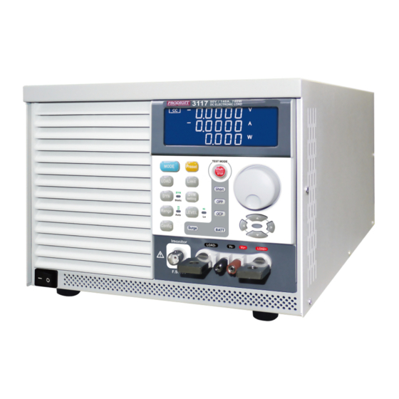
3110 Series
Plug-In Electronic
Load Operation manual
S/N:900311002
REV:A
Table of
Contents
Previous
Page
Next
Page
1
2
3
4
5
Advertisement
Table of Contents
Need help?
Do you have a question about the 3110 Series and is the answer not in the manual?
Ask a question
Questions and answers
Related Manuals for Prodigit 3110 Series
Laboratory Equipment Prodigit 3111 Operation Manual
Plug-in electronic load (106 pages)
Laboratory Equipment Prodigit 3117 Operation Manual
Plug-in electronic load (106 pages)
This manual is also suitable for:
3110
3111
3114
3117
3119
Table of Contents
Print
Rename the bookmark
Delete bookmark?
Delete from my manuals?
Login
Sign In
OR
Sign in with Facebook
Sign in with Google
Upload manual
Upload from disk
Upload from URL


Need help?
Do you have a question about the 3110 Series and is the answer not in the manual?
Questions and answers