Table of Contents
Advertisement
Advertisement
Table of Contents

Related Manuals for Prodigit 3111


Summarization of Contents
Chapter 1 Introduction
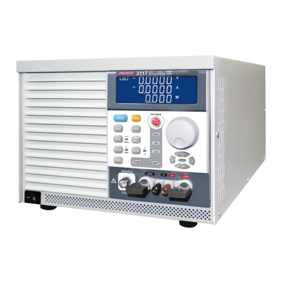
1-1 General description
Overview of the 3110 series electronic loads, their capabilities, and market response.
1-2 Features
Highlights the key functionalities and capabilities of the 3110 series load modules.
1-3 Standard Accessories
Lists all the standard accessories provided with the 3110 series electronic load.
1-4 Specifications
Presents detailed technical specifications for the 3110 series electronic load modules.
Chapter 2 Installation
2-1 Check line voltage
Instructions for verifying and setting the correct line voltage for the 3110 series.
2-2 Input Fuse
Procedure for checking and replacing the mains input fuse in the 3110 series.
2-3 Environmental requirements
Specifies the indoor usage conditions and environmental limitations for the 3110 series.
2-4 Observe the International Electrical Symbol listed below.
Guidance on understanding and observing international electrical safety symbols.
2-5 Cleaning
Instructions for safely cleaning the 3110 series electronic load module.
2-6 Power Up
Steps to follow for safely powering up the 3110 series electronic load.
2-7 RS232 & USB Interface
Description of the RS232 and USB interfaces on the rear panel of the 3110 series.
2-8 Load wire inductance
Explanation of load wire inductance effects and how to mitigate them.
Chapter 3 Operation
3-1. Dimension
Provides the physical dimensions of the 3110, 3111, and 3114 load modules.
3-2. Front panel LCD description
Details the layout and function of the front panel LCD display on the 3110 series.
3-4. Input terminal and wire consideration
Guidance on selecting appropriate input terminals and wire sizes for safe operation.
3-5. Protection features
Describes the various built-in protection mechanisms of the 3110 series electronic load.
3-3. Initial setting of 3110 series load module
Details the default factory settings for various parameters of the 3110 series load modules.
Chapter 4 Communication Interface programming operation
4-1. Introduction
Introduction to the computer interface options (RS232, USB) for remote control.
4-2. RS232 Set-up
Configuration details for setting up the RS232 serial communication interface.
4-5. The description of abbreviation
Explains abbreviations and symbols used in communication interface commands.
4-6. Communication Interface programming command syntax description
Describes the syntax rules and structure for programming commands.
4-7. Communication Interface programming command description
Detailed description of specific communication interface commands.
4-3. 3110 series Communication Interface programming command list 1
Lists the first set of simple format commands for remote programming.
4-4. Communication Interface programming command list 2
Lists the second set of complex format commands for remote programming.
Chapter 5 Applications
5-1. Local sense connections
Explains how to establish local sense connections for voltage measurement.
5-2. Remote sense connections
Details remote sense connections for compensating voltage drop over long leads.
5-3. Constant Current mode application
Applications and operating instructions for the Constant Current (CC) mode.
5-4. Constant Resistance mode application
Applications and operating instructions for the Constant Resistance (CR) mode.
5-5. Constant Voltage mode application
Applications and operating instructions for the Constant Voltage (CV) mode.
5-6. Constant Power mode application
Applications and operating instructions for the Constant Power (CP) mode.
5-7. Zero-Volt loading application
Description of the zero-volt loading application for battery testing.
5-8. 3110 series electronic load OCP, OPP, SHORT operation flow Chart
Flow chart illustrating the operation of OCP, OPP, and SHORT tests.
Need help?
Do you have a question about the 3111 and is the answer not in the manual?
Questions and answers