Table of Contents
Advertisement
Quick Links
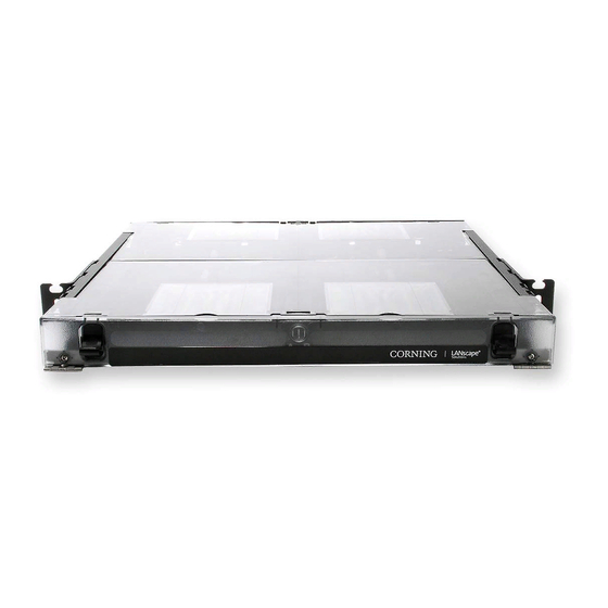
closet connector Housings
(ccH) 1U/2U/3U Quick
Start Guide
p/n 003-876-QSG, Issue 4
Visit http://www.corning.com/opcomm/resources/Standard recommended Procedures for the in-depth
installation manual and other language versions. Search for part number 003-876.
1.
CARTON CONTENTS
1
Sliding cover
6
Sliding tray
Label card
2
7
Slack management clip
3
Mounting bracket
8
Internal strain-relief assembly
Door latch
4
9
Transitional strain-relief holder
5
Blank adapter panel
10
External strain-relief assembly
6
3
1
5
11
2
4
2.
MOUNTING THE HOUSING
Install two #12-24 x 0.5
Slide mounting bracket notch
2a
2b
Phillips-head screws
over screw heads.
at desired height.
Leave gap behind head.
2b
2a
STANDARD RECOMMENDED PROCEDURE 003-876-QSG | ISSUE 4 | OctOber 2017 | PAGE 1 OF 2
3.
ACCESSING THE HOUSING
Open front and rear doors.
3a
Pull covers with moderate force
in opposite directions to remove.
11
Jumper guide
Slide tray toward rear of housing.
3c
Press latches on both sides to release tray
and pull it completely out of housing.
8
9
7
10
Press here.
5
3
4.
INSTALLING CABLE FOR FIELD TERMINATION
11
WARNING: Never look directly into the end of a fiber that may be carrying laser light.
4
Laser light can be invisible and can damage your eyes. Viewing it directly does not cause pain.
TPA-3873
the iris of the eye will not close involuntarily as when viewing a bright light. consequently,
serious damage to the retina of the eye is possible. Should accidental eye exposure to laser
light be suspected, arrange for an eye examination immediately.
Install next two screws in
2c
center notch of mounting
bracket; tighten all screws.
4.1. Accessing the Cable for Field Termination
Strip Lengths for 1U, 2U, 3U Housings
2c
CABLE
OSP, FREEDM
MIC
®
, UMIC Cable or Subunit
TPA-3874
Lift plunger on internal strain-relief assembly.
3b
Push bracket to rear to disengage and remove
it from the housing.
Plunger
Set tray and strain-relief assembly on work
3d
surface for next operations.
Press here.
Strain-relief
Direct Termination
Point
Fan-out body legs available
22 inches (internal strain-relief)
in 25 - 48 inches lengths
24 inches (external strain-relief)
®
22 inches (internal strain-relief)
24 inches (external strain-relief)
Strip to 48 inches
4.2. Sheath Retention
4.3. Strain-relieving to the Transitional Strain-Relief Holder
TPA-3875
Replace blank panels with adapter
4.3a
panels applicable for the
connectors being used.
4.3a
4.3a
TPA-3876
OR Secure loose tube
Press buffer tube
4.3b
cable to the transitional
fan-out bodies into
transitional holder.
holder with cable ties.
In 2U or 3U housings,
TPA-3877
4.3c
you may stack the
transitional holder to
accommodate more
fan-out bodies or cables.
TPA-3883
Advertisement
Table of Contents

Subscribe to Our Youtube Channel
Related Manuals for CORNING 1U


Summary of Contents for CORNING 1U
- Page 1 4.3c you may stack the 4.3a Leave gap behind head. transitional holder to accommodate more fan-out bodies or cables. Strip Lengths for 1U, 2U, 3U Housings Strain-relief Direct Termination CABLE Point Fan-out body legs available 22 inches (internal strain-relief) in 25 - 48 inches lengths...
- Page 2 A complete listing of the trademarks of Corning Optical Communications is available at www.corning.com/opcomm/trademarks. All other trademarks are the properties of their respective owners. Corning Optical Communications is ISO 9001 certified. © 2011, 2017 Corning Optical Communications.
Need help?
Do you have a question about the 1U and is the answer not in the manual?
Questions and answers