Table of Contents
Advertisement
Quick Links
related literature | Search www.corning.com/opcomm. Click on "Resources."
003-888-AEN
000-276-AEN
003-825-AEN
003-892-AEN
003-1049-AEN
000-274-AEN
003-885-AEN
006-407-QSG-AEN
003-991-AEN
Table of Contents
1.
General . . . . . . . . . . . . . . . . . . . . . . . . . . . . . . . . . . . . . . . . . . . . . . . . . . . . . . . . . . . . . . . . . . . . . . . . . . . . . . . . . . . . . . . . . . . . . . . . . . 2
2.
Carton Contents . . . . . . . . . . . . . . . . . . . . . . . . . . . . . . . . . . . . . . . . . . . . . . . . . . . . . . . . . . . . . . . . . . . . . . . . . . . . . . . . . . . . . . . . . . 2
3.
Tools and Materials Required . . . . . . . . . . . . . . . . . . . . . . . . . . . . . . . . . . . . . . . . . . . . . . . . . . . . . . . . . . . . . . . . . . . . . . . . . . . . . . 2
3.1
Tools . . . . . . . . . . . . . . . . . . . . . . . . . . . . . . . . . . . . . . . . . . . . . . . . . . . . . . . . . . . . . . . . . . . . . . . . . . . . . . . . . . . . . . . . . . . . . . 2
3.2
Materials . . . . . . . . . . . . . . . . . . . . . . . . . . . . . . . . . . . . . . . . . . . . . . . . . . . . . . . . . . . . . . . . . . . . . . . . . . . . . . . . . . . . . . . . . . 2
4.
Installation . . . . . . . . . . . . . . . . . . . . . . . . . . . . . . . . . . . . . . . . . . . . . . . . . . . . . . . . . . . . . . . . . . . . . . . . . . . . . . . . . . . . . . . . . . . . . . 3
4.1
Rack or Frame Mounting . . . . . . . . . . . . . . . . . . . . . . . . . . . . . . . . . . . . . . . . . . . . . . . . . . . . . . . . . . . . . . . . . . . . . . . . . . . . 3
4.2
Install Trunk Cables . . . . . . . . . . . . . . . . . . . . . . . . . . . . . . . . . . . . . . . . . . . . . . . . . . . . . . . . . . . . . . . . . . . . . . . . . . . . . . . . . 3
4.2.1
Trunk Cable Placement with the Pulling Grip . . . . . . . . . . . . . . . . . . . . . . . . . . . . . . . . . . . . . . . . . . . . . . . . . .5
4.2.2
Pulling Grip Removal . . . . . . . . . . . . . . . . . . . . . . . . . . . . . . . . . . . . . . . . . . . . . . . . . . . . . . . . . . . . . . . . . . . . . . . 6
4.3
(OPTIONAL) Install CDF Bracket . . . . . . . . . . . . . . . . . . . . . . . . . . . . . . . . . . . . . . . . . . . . . . . . . . . . . . . . . . . . . . . . . . . . . . .7
4.4
Install Trunk Cables from Either Side of the Housing . . . . . . . . . . . . . . . . . . . . . . . . . . . . . . . . . . . . . . . . . . . . . . . . . . . 8
4.4.1
Installing Trunk Cable Using Keyhole Cradle . . . . . . . . . . . . . . . . . . . . . . . . . . . . . . . . . . . . . . . . . . . . . . . . . . 8
4.4.2
Installing Trunk Cable with Keyhole Adapter . . . . . . . . . . . . . . . . . . . . . . . . . . . . . . . . . . . . . . . . . . . . . . . . . . 9
4.5
Install Trunk Cables from Rear of Housing . . . . . . . . . . . . . . . . . . . . . . . . . . . . . . . . . . . . . . . . . . . . . . . . . . . . . . . . . . . . . . . . . . . . 10
4.6
(OPTIONAL) Remove Housing Trunk Plate . . . . . . . . . . . . . . . . . . . . . . . . . . . . . . . . . . . . . . . . . . . . . . . . . . . . . . . . . . . . . . . . . . . . . 1 1
4.7
Install EDGE™ Modules . . . . . . . . . . . . . . . . . . . . . . . . . . . . . . . . . . . . . . . . . . . . . . . . . . . . . . . . . . . . . . . . . . . . . . . . . . . . . . . . . . . . . . 12
4.7.1
Into EDGE-01U-SP, EDGE-02U and EDGE-04U Housings . . . . . . . . . . . . . . . . . . . . . . . . . . . . . . . . . . . . . . . . . . . . . 12
4.7.2
Into EDGE-01U Housing . . . . . . . . . . . . . . . . . . . . . . . . . . . . . . . . . . . . . . . . . . . . . . . . . . . . . . . . . . . . . . . . . . . . . . . . . . . . 13
4.7.3
Connect Jumpers to EDGE™ Modules . . . . . . . . . . . . . . . . . . . . . . . . . . . . . . . . . . . . . . . . . . . . . . . . . . . . . . . . . . . . . . . 14
4.8
4.8.1
Connecting MTP Trunk Cable to Rear of MTP Adapter Panel - Initial Mating . . . . . . . . . . . . . . . . . . 16
4.8.2
Extender Trunk to the Front of MTP Adapter Panels - Initial Mating . . . . . . . . . . . . . . . . . . . . . . . . . . .18
5.
Recordkeeping . . . . . . . . . . . . . . . . . . . . . . . . . . . . . . . . . . . . . . . . . . . . . . . . . . . . . . . . . . . . . . . . . . . . . . . . . . . . . . . . . . . . . . . . . . 19
5.1
Hardware Labeling . . . . . . . . . . . . . . . . . . . . . . . . . . . . . . . . . . . . . . . . . . . . . . . . . . . . . . . . . . . . . . . . . . . . . . . . . . . . . . . . 19
5.2
Cable/Jumper Labeling . . . . . . . . . . . . . . . . . . . . . . . . . . . . . . . . . . . . . . . . . . . . . . . . . . . . . . . . . . . . . . . . . . . . . . . . . . . . 23
6.
Troubleshooting and Maintenance . . . . . . . . . . . . . . . . . . . . . . . . . . . . . . . . . . . . . . . . . . . . . . . . . . . . . . . . . . . . . . . . . . . . . . . . 24
6.1
Testing . . . . . . . . . . . . . . . . . . . . . . . . . . . . . . . . . . . . . . . . . . . . . . . . . . . . . . . . . . . . . . . . . . . . . . . . . . . . . . . . . . . . . . . . . . . 24
6.2
Replace EDGE™ Module . . . . . . . . . . . . . . . . . . . . . . . . . . . . . . . . . . . . . . . . . . . . . . . . . . . . . . . . . . . . . . . . . . . . . . . . . . . . 25
6.3
Remove Trunk Cable . . . . . . . . . . . . . . . . . . . . . . . . . . . . . . . . . . . . . . . . . . . . . . . . . . . . . . . . . . . . . . . . . . . . . . . . . . . . . . . 26
6.3.1
Cable in Keyhole Cradle . . . . . . . . . . . . . . . . . . . . . . . . . . . . . . . . . . . . . . . . . . . . . . . . . . . . . . . . . . . . . . . . . . . . 26
6.4
Changing the Polarity of an LC Uniboot Connector . . . . . . . . . . . . . . . . . . . . . . . . . . . . . . . . . . . . . . . . . . . . . . . . . . . 26
6.5
Changing the Polarity of an MTP Adapter and Connector . . . . . . . . . . . . . . . . . . . . . . . . . . . . . . . . . . . . . . . . . . . . . 27
6.6
Connector Care and Cleaning - Post Initial Mating . . . . . . . . . . . . . . . . . . . . . . . . . . . . . . . . . . . . . . . . . . . . . . . . . . 27
EDGE™ Solution with 1U/2U/4U Fixed Trays
EDGE Secure Solutions FTTD Module
EDGE and EDGE8® Fiber Zone Boxes
EDGE and EDGE8 Solution Single Module Housing
EDGE Solution Single Module Housing for Splicing
EDGE Splice Cassette/EDGE Field-Terminated Cassette
EDGE Solution Modules in an Enhanced Management Frame
Field Tool for MTP® PRO Connectors Quick Start Guide
EDGE Port Replication Housing
Adapter Panels . . . . . . . . . . . . . . . . . . . . . . . . . . . . . . . . . . . . . . . . . . . . . . . . . . . . . . . . . . . . . . . . . . . . . . . . .15
®
EDGE™ Solution
p
p/n 003-794-AEN, Issue 14
Standard Recommended Procedure 003-794-AEN | Issue 14 | March 2020 | Page 1 of 27
Advertisement
Table of Contents

Related Manuals for CORNING EDGE Series


Summary of Contents for CORNING EDGE Series
-
Page 1: Table Of Contents
EDGE™ Solution p/n 003-794-AEN, Issue 14 related literature | Search www.corning.com/opcomm. Click on “Resources.” 003-888-AEN EDGE™ Solution with 1U/2U/4U Fixed Trays 000-276-AEN EDGE Secure Solutions FTTD Module 003-825-AEN EDGE and EDGE8® Fiber Zone Boxes 003-892-AEN EDGE and EDGE8 Solution Single Module Housing... -
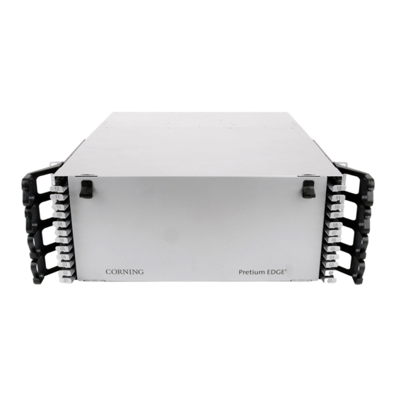
Page 2: General
General Figure 1 — EDGE Housings This document describes installation of the EDGE™ 1U, 1U-SP, 2U, and 4U Housing Solutions (Figure 1). Except where installation of another housing is unique, only the 4U housing is illustrated. Carton Contents • Housing, either 1U, 1U-SP, 2U, or 4U rack-height •... -
Page 3: Installation
Installation Rack or Frame Mounting Step 1: Identify the position on the rack where the housing will be installed and partially install screws to rest the mounting brackets on Figure 2. Step 2: Move brackets forwards or backwards for desired frontal projection and rest the mounting brackets behind the screw heads just installed in the rack. - Page 4 Weather Precautions • Always follow the recommended storage temperature guidelines for the cable when storing a trunk/pigtail. Each cable type will have a storage temperature rating that can be found on the product specification sheets. Storage outside of these ranges can cause damage to the cables.
-
Page 5: Trunk Cable Placement With The Pulling Grip
CAUTION: Fiber optic cable is sensitive to excessive pulling, bending, and crushing forces. Consult the cable specification sheet for the cable you are installing. Do not bend the cable more sharply than the minimum recommended bend radius. Do not apply more pulling force to the cable than specified. Do not crush the cable or allow it to kink. -
Page 6: Pulling Grip Removal
4.2.2 Pulling Grip Removal Step 1: Remove the pull line and clean any dirt or debris from the outer surfaces of the sleeve. IMPORTANT: Disassemble the pulling sleeve on a work surface free from dirt, excessive heat, or any solvents. Step 2: Lift the hook-and-loop flaps to expose the zipper pull. -
Page 7: (Optional) Install Cdf Bracket
96- and 144-fiber Trunks: Step 8: Starting with the mesh bag closest to the furcation body, remove the tape and mesh to expose the first set of three folded legs (Figure 10). Unfold the legs from around the bend control device. Repeat this step on the middle mesh bag, and then conclude by removing the end mesh bag. -
Page 8: Install Trunk Cables From Either Side Of The Housing
Figure 11 — Install CDF Bracket Install Trunk Cables from Either Side of the Housing If necessary to install trunk cables from the rear of a housing, refer to Section 4.5 for details on reorienting the backplates to accommodate rear cable entry. In a 4U housing trunk cables may be installed into the backplates in the top of the housing in an upside-down orientation, if desired or necessary, to accommodate additional cables. -
Page 9: Installing Trunk Cable With Keyhole Adapter
Step 3: Open rear housing door. Route cables into housing through side openings. Figure 13 — Install Trunk Cables with Keyhole Cradle Step 4: Insert cradle feet into backplate and slide into slots to lock in place. Step 5: Repeat for all trunk cables and allow connectorized MTP legs to flow out the rear of the housing until ready to mate in the appropriate module or panel. -
Page 10: Install Trunk Cables From Rear Of Housing
Install Trunk Cables from Rear of Housing If rear cable entry into the housing is desired or necessary, the backplates must be turned 180 degrees before installing the cables. Step 1: Remove existing backplates by removing the four screws (Figure 15). Step 2: Turn the backplate 90 degrees as shown and reinstall the four screws. -
Page 11: (Optional) Remove Housing Trunk Plate
(OPTIONAL) Remove Housing Trunk Plate If cable entry strain-relief is accomplished in a location external to the housing, the trunk plate may be removed to allow more room behind the housing (Figure 16). Step 1: (For 4U housing only) Remove side panel from each side of the housing. Step 2: Remove any screws holding the access panels to the housing. -
Page 12: Install Edge™ Modules
Remove the MTP®connector dust cap by pulling on the dust cap while holding the connector body. For the initial mating, do not clean or scope connectors. Corning® CleanAdvantage™ connectors are shipped with an optimized dust cap to maintain cleanliness for the first use. -
Page 13: Into Edge-01U Housing
CAUTION: When removing the trays, position yourself in the center of the rack and use both hands to pull the tray out. Step 7: Return to front of housing and pull out each tray to test that tray freely pulls out without stress on the cables. -
Page 14: Connect Jumpers To Edge™ Modules
For the initial mating, do not clean or scope connectors. Corning CleanAdvantage™ connectors are shipped with an optimized dust cap to maintain cleanliness for the first use. CAUTION: Scoping Corning CleanAdvantage connectors increases the risk of adding contamination to the system. -
Page 15: Install Mtp
Step 4: Route jumper legs, right and/or left out either side of the housing. (Do NOT cross legs in opposite directions.) Store legs in clips at front of tray (Figure 20, step 3). NOTE: Inspect the jumpers during the routing process to ensure no kinking occurred. If a kink has occurred, re- route the jumper leg to remove the kink. -
Page 16: Connecting Mtp Trunk Cable To Rear Of Mtp Adapter Panel - Initial Mating
4.8.1 Connecting MTP Trunk Cable to Rear of MTP Adapter Panel — Initial Mating Figure 21 — Install MTP Trunk Cables into Adapter Panel. Standard Recommended Procedure 003-794-AEN | Issue 14 | March 2020 | Page 16 of 27... - Page 17 (See page 12, Figure 16A) For the initial mating, do not clean or scope connectors. Corning CleanAdvantage™ connectors are shipped with an optimized dust cap to maintain cleanliness for the first use. Keep dust caps in place on the front of the adapter panel, if applicable.
-
Page 18: Connecting Harnesses, Mtp Jumper, Mtp Conversion Harnesses Or
(See page 12, Figure 16A) For the initial mating, do not clean or scope connectors. Corning CleanAdvantage™ connectors are shipped with an optimized dust cap to maintain cleanliness for the first use. -
Page 19: Recordkeeping
Figure 24 — Typical Harness Configurations Recordkeeping Detailed and accurate recordkeeping enables users to logically “map” fiber terminations within the Data Center from Local equipment to Remote equipment. It is recommended that users employ labeling guidelines outlined in ANSI/TIA-606-A-1 for mapping the network. Guidelines below provide an analogous solution in accordance with this standard for labeling to be used with the EDGE™... - Page 20 • Modules or MTP® panels come assembled with adapters and silkscreened with Fiber and/or Port • Housing/chassis comes equipped with a label card that is easily removable from the inside of the front door and requires no additional fastening to remain in place. This label may be written on, but use of a label maker is better.
- Page 21 Step 1: Frame/Cabinet Location (Figure 26) Identify location of Frame or Cabinet within the floor space grid coordinate system. Preprint labels and adhere to Front and Back of Frame or Cabinet at the top and bottom. Figure 26 — Frame/Cabinet Label Location Step 2: Housing/Chassis Location (Figure 27) Identify location within the Frame or Cabinet (in rack units from the bottom) by locating the Top/Left...
- Page 22 Step 3: Tray Location (Figure 28)) Identify location of tray within the housing/chassis. Trays come pre-labeled 01 to 12 from the bottom to the top of the chassis. Figure 28 —Tray Label Location Step 4: Module Location with Fiber or Port Range (Figure 29) Each tray comes pre-labeled A through D to identify Module position within the tray.
-
Page 23: Cable/Jumper Labeling
Step 5: Documentation (Figure 30) Identify remote location termination and determine code to be printed. It should only be necessary to print the remote location. Printed code from label makers may be affixed to the label card on the inside of the front door. Figure 30 —... -
Page 24: Troubleshooting And Maintenance
Troubleshooting and Maintenance Testing Use the Fluke MultiFiber™ Pro Optical Power Meter and Test Kits for testing the MTP connections. Follow the ® Fluke Networks manual which can be found on-line at http://download.flukenetworks.com/Download/Asset/MultiFiberPro_9827313_ENG_A_W.PDF. A sample test procedure can be seen in Figure 31. * Figure 31 —... -
Page 25: Replace Edge™ Module
Replace EDGE™ Module Step 1: Open front door and pull tray out. Step 2: Press latch on LC connector and pull connector out (Figure 32). If jumper is equipped with MTP connector, simply grasp connector body and pull connector out of the adapter. (NOTE: only LC connectors shown in Figure 30.) Press lever on right side of module and pull module out. -
Page 26: Remove Trunk Cable
Remove Trunk Cable 6.3.1 Cable in Keyhole Cradle If necessary to replace trunk cable or keyhole cradle, remove per the directions in this section (Figure 33). Install new cable or cradle per the directions in Section 4.4. Step 1: Pull back on both latches while pushing cradle in opposite direction. Lift cradle and cable up. Step 2: Open cradle door. -
Page 27: Changing The Polarity Of An Mtp Adapter And Connector
A complete listing of the trademarks of Corning Optical Communications is available at www.corning.com/opcomm/trademarks. All other trademarks are the properties of their respective owners. Corning Optical Communications is ISO 9001 certified. © 2009, 2019, 2020 Corning Optical Communications. All rights reserved...
Need help?
Do you have a question about the EDGE Series and is the answer not in the manual?
Questions and answers