Pfeiffer Vacuum TPG 300 Operating Instructions Manual
Plug-in boards, total pressure measuring and control unit
Hide thumbs
Also See for TPG 300:
- Operating instructions manual (86 pages) ,
- Operating instructions manual (50 pages)

Related Manuals for Pfeiffer Vacuum TPG 300


Summary of Contents for Pfeiffer Vacuum TPG 300
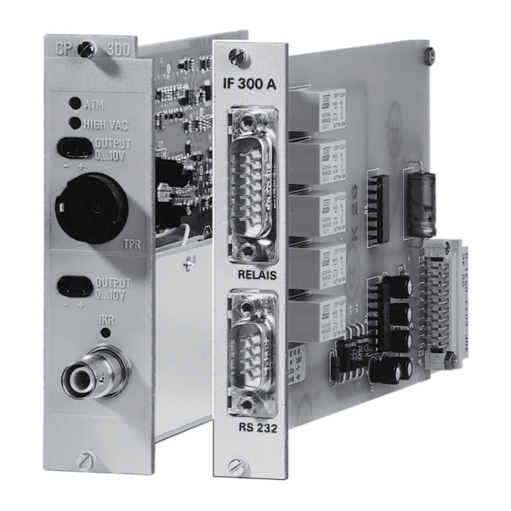
- Page 1 OPERATING INSTRUCTIONS Translation of the Original PLUG-IN BOARDS for total pressure measuring and control units TPG 300/TPG 500...
- Page 2 Dear Customer, Thank you for choosing a Pfeiffer Vacuum product. Your new total pressure measuring and control unit should support you in your individual application with full performance and without malfunctions. The name Pfeiffer Vacuum stands for high-quality vacuum technology, a comprehensive and complete range of top-quality products and first-class service.
-
Page 3: Table Of Contents
Foreseeable improper use Responsibilities and warranty Owner requirements Personnel qualification 2.8.1 Ensuring personnel qualification 2.8.2 Personnel qualification for maintenance and repair 2.8.3 Advanced training with Pfeiffer Vacuum Operator requirements Product description Function 3.1.1 Pirani measuring system 3.1.2 Cold cathode measuring system... - Page 4 5.3.6 Connecting the "Profibus-DP" interface on the IF 300P Calibrating the Pirani measuring circuit Malfunctions Shipping Recycling and disposal General disposal information Disposing of plug-in boards Service solutions by Pfeiffer Vacuum Accessories 11.1 Accessory information 11.2 Ordering accessories Technical data and dimensions 12.1 Technical data 12.2 Dimensions Appendix 13.1 Relation: measuring signal and pressure...
- Page 5 List of tables List of tables Tbl. 1: Applicable documents Tbl. 2: Variants Tbl. 3: Abbreviations used Tbl. 4: Switch functions on IF 300A/C/P Tbl. 5: Switching functions on IF 300B Tbl. 6: Disturbances during installation Tbl. 7: Interference during operation and calibration Tbl.
- Page 6 List of figures List of figures Fig. 1: "OUTPUT" connection with 2 sockets Fig. 2: "CONTROL" connection on PE 300DC9 Fig. 3: Switch and logic on the "CONTROL" connection Fig. 4: "RELAY" connection on IF 300A/C/P Fig. 5: "RELAY" connection on IF 300B Fig.
-
Page 7: About This Manual
Tbl. 2: Variants You can find the part number on the rating plate of the product. Pfeiffer Vacuum reserves the right to make technical changes without prior notification. The figures in this document are not to scale (dimensions in mm). 7/48... -
Page 8: Target Group
About this manual 1.2 Target group These operating instructions are aimed at all persons performing the following activities on the product: ● Transportation ● Setup (Installation) ● Usage and operation ● Decommissioning ● Maintenance and cleaning ● Storage or disposal The work described in this document is only permitted to be performed by persons with the appropriate technical qualifications (expert personnel) or who have received the relevant training from Pfeiffer Vac- uum. -
Page 9: Trademark Proof
About this manual Abbreviation Explanation RS-232 Recommended Standard 232 (Standard for a serial interface often available on computers) RS-422 Recommended Standard 422 (Interface standard for a wired differential serial data transfer) Received eXchange Data (incoming data line) Safe High Voltage (connector for coax cable) Total Pressure Gauge (total pressure measuring and control unit) Transmitted eXchange Data (outgoing data line) Tbl. -
Page 10: Safety
Safety instructions according to product’s life stages All safety instructions in this document are based on the results of a risk assessment. Pfeiffer Vacuum has taken into account all the relevant life stages of the product. Risks during installation DANGER Danger to life due to dangerous contact voltage Voltages above 30 V (AC) or 60 V (DC) are considered dangerous in accordance with EN 61010. -
Page 11: Safety Precautions
2.4 Proper use The plug-in boards are analog measuring, interface and relay boards for the ModulLine total pressure measuring and control units TPG 300 and TPG 500. ► Install, operate and maintain the product only in accordance with these operating instructions. -
Page 12: Responsibilities And Warranty
Safety 2.6 Responsibilities and warranty Pfeiffer Vacuum shall assume no responsibilities and warranty if the operating company or a third party: ● disregards this document. ● does not use the product for its intended purpose. ● carries out any modifications to the product (conversions, changes, maintenance work, etc.) that are not listed in the corresponding operating instructions. -
Page 13: Personnel Qualification For Maintenance And Repair
─ Customer with Pfeiffer Vacuum service training ─ Pfeiffer Vacuum service technician 2.8.3 Advanced training with Pfeiffer Vacuum For optimal and trouble-free use of this product, Pfeiffer Vacuum offers a comprehensive range of courses and technical trainings. For more information, please contact Pfeiffer Vacuum technical training. -
Page 14: Product Description
3.2 Identifying the product You will need all the data from the rating plate to safely identify the product when communicating with Pfeiffer Vacuum. 1. Read the data on the product rating plate. 2. Record this data. -
Page 15: Interfaces
Product description Interfaces and relay boards There are 4 types of interface and relay boards: ● 2 with RS-232-C interfaces ● 1 with RS-422 interface ● 1 with Profibus-DP interface All 4 types each have 5 relays with potential-free switching contacts. The types each have a different switching voltage for the relays and different interface connections. -
Page 16: Relay" Connection On If 300A/C/P
Product description 3.4.3 "RELAY" connection on IF 300A/C/P Screen Fig. 4: "RELAY" connection on IF 300A/C/P The figure shows the contacts in rest position. Pins Designation Switching function Relay 1 Relay 2 Relay 3 Relay 4 Relay 5 Error status Tbl. 4: Switch functions on IF 300A/C/P 3.4.4 "RELAY"... -
Page 17: Rs-232" Connection On If 300A
Product description Pins Designation Switching function Relay 4 Relay 5 Error status Tbl. 5: Switching functions on IF 300B 3.4.5 "RS-232" connection on IF 300A IF 300A S GND S GND Screen Computer Fig. 6: "RS-232" connection on IF 300A 2 Receive data (RxD) Signal ground (S GND) (relating to the measuring device) 3 Transmit data (TxD) -
Page 18: Rs-422" Connection On If 300C
Product description 3.4.7 "RS-422" connection on IF 300C IF 300C P GND S GND RX– TX– Screen Fig. 8: "RS-422" connection on IF 300C Protective ground (P GND) Reception data (Rx-) (relating to the measuring device) 2, 3, 4 unassigned Transmission data (Tx+) (relating to the measuring device) Signal ground (S GND) Transmission data (Tx)-... -
Page 19: Scope Of Delivery
Product description IF 300P Fig. 9: "Profibus" connection on IF 300P 1 Screen VP (only required with bus end devices) 2 Do not connect Do not connect 3 RxD/TxD-P (Line B) RxD/TxD-N (Line A) 4 CNTR-P (optional) Do not connect 5 DGND 3.5 Scope of delivery The shipment includes the following parts:... -
Page 20: Transport And Storage
Transport and storage 4 Transport and storage 4.1 Transporting the product NOTICE Damage caused by incorrect transportation Transportation in unsuitable packaging, or failure to install all transport locks, can damage the prod- uct. ► Comply with the instructions for safe transportation. Packing We recommend keeping the transport packaging and original protective cover. -
Page 21: Installation
Installation 5 Installation 5.1 Installing/removing plug-in boards NOTICE Damage to unit from electrostatic discharge Electrostatic discharge damages electronic components. Defects resulting from failure to comply with this warning result in loss of any warranty claim entitlement. ► Carry out all work on ESD-protected workstations only, in compliance with the appropriate work- ing methods. -
Page 22: Connecting The Cold Cathode Gauge
Installation Procedure 1. Make sure that the TPG is switched off. 2. Despite being partially screened, do not lay the gauge cable parallel with cables with too much interference. 3. Connect the gauge with the measuring cable to the "IKR" connection on the measurement board. 4. -
Page 23: Connecting Interfaces And Connections
With voltages < 50 V, you may use 4.8 × 0.8 mm insulated flat pin terminals. However, Pfeiffer Vacuum recommends using the relay plug, as the relay plug enables fast discon- nection of the connection as well as strain relief. -
Page 24: Connecting The "Rs-232-C" Interface Of The If 300A
Installation Connecting relays (IF 300B) Screened cable is not required for the connection. 1. Only carry out work on the plug when it is de-energized. 2. In general, use the relay plug for voltages ≥ 50 V for safety reasons. 3. -
Page 25: Connecting The "Profibus-Dp" Interface On The If 300P
Installation 4. Make sure that components to be connected externally contain the technical data of the plug-in board. 5. Use a suitable interface cable to connect the interface. 5.3.6 Connecting the "Profibus-DP" interface on the IF 300P Details on the Profibus-DP interface You can find details on the Profibus-DP interface in the corresponding communication pro- tocol. -
Page 26: Calibrating The Pirani Measuring Circuit
Pirani measuring circuit. This will in turn necessitate recalibration or cleaning. Pfeiffer Vacuum has calibrated the gauge to standard values at the factory. However, as a result of indi- vidual scattering, gauge tolerances, gauge contamination or different cable lengths, you must accept deviations. -
Page 27: Malfunctions
Malfunctions 7 Malfunctions Warranty Malfunctioning of the equipment as a direct result of contamination or wear, as well as wear parts, is not covered by the warranty. Disturbance Possible cause Remedy Gauge cable will not connect to IKR gauge. Old IKR gauge with MHV Use a correct cable. -
Page 28: Tbl. 9: Disturbances With The Rs-232-C Interface
TPG 300 firmware: 302-654 Profibus firmware: V1.5 Set the correct Baud rate (19200 Baud). Incorrect Baud rate set Tbl. 11: Disturbances with the Profibus-DP interface On TPG 300 basic unit, from firmware 302-654. On TPG 300 basic unit, from firmware 302-654. 28/48... -
Page 29: Shipping
► Comply with the instructions for safe shipping. Decontamination subject to charge Pfeiffer Vacuum decontaminates products not clearly declared "Free of contamination" at your expense. Instructions for safe shipping ► Do not ship microbiological, explosive or radioactively contaminated products. -
Page 30: Recycling And Disposal
– Fluoroelastomers (FKM) – Potentially contaminated components that come into contact with media 9.2 Disposing of plug-in boards Pfeiffer Vacuum plug-in boards contain materials that you must recycle. 1. Separate the components into recyclable materials. 2. Recycle the components. 3. Dispose of the product or components in a safe manner according to locally applicable regula- tions. -
Page 31: Service Solutions By Pfeiffer Vacuum
We are always focused on perfecting our core competence – servicing of vacuum components. Once you have purchased a product from Pfeiffer Vacuum, our service is far from over. This is often exactly where service begins. Obviously, in proven Pfeiffer Vacuum quality. - Page 32 Service solutions by Pfeiffer Vacuum 5. Prepare the product for transport in accordance with the provisions in the contamination declaration. a) Neutralize the product with nitrogen or dry air. b) Seal all openings with blind flanges, so that they are airtight.
-
Page 33: Accessories
Measurement cable in standard and high temperature versions in different lengths, for connecting to a Pfeiffer Vacuum total pressure measuring and control unit or an ionization measuring device Dummy plates Cover plate for free slots on Pfeiffer Vacuum total pressure measuring and control units that are not fully configured 11.2 Ordering accessories... -
Page 34: Tbl. 13: Cold Cathode Gauges
Accessories Description Order number suitable for measure- ment boards Cold cathode gauge head IKR 070, triaxial, metal PT R20 501 CP 300T11, CP 300T11L seal, DN 40 ISO-KF Cold cathode gauge head IKR 070, triaxial, metal PT R20 502 CP 300T11, CP 300T11L seal, DN 40 CF-F Tbl. -
Page 35: Tbl. 15: Measuring Cable For Tpr 017 And Tpr 018
Accessories Description Order number Measurement Cable, TPR 017/018, 30 m, 80 °C PT 548 460-T Measurement Cable, TPR 017/018, 35 m, 80 °C PT 548 461-T Measurement Cable, TPR 017/018, 40 m, 80 °C PT 548 462-T Measurement Cable, TPR 017/018, 45 m, 80 °C PT 548 463-T Measurement Cable, TPR 017/018, 50 m, 80 °C PT 548 464-T... -
Page 36: Tbl. 18: Measuring Cable For Ikr 070
Accessories Description Order number Measurement Cable, IKR 070, 45 m, 80 °C PT 548 495-T Measurement Cable, IKR 070, 50 m, 80 °C BP 229 748-T Triax cable with triax plugs, test voltage: 6 kV DC Tbl. 18: Measuring cable for IKR 070 Description Order number D-sub plug, female, 15-pin, for IF 300 A/C, relay output... -
Page 37: Technical Data And Dimensions
Technical data and dimensions 12 Technical data and dimensions 12.1 Technical data Parameter Value/designation Measuring board PI 300D for Pirani gauges with wolfram fila- ment PI 300DN for Pirani gauges with nickel fila- ment Number of measuring circuits Measuring range (N equivalent) 1000 hPa to 8 ×... - Page 38 Technical data and dimensions Parameter Value/designation Number of measuring circuits 1 each of Measuring range (N equivalent) Pirani 1000 hPa to 8 × 10 Cold cathode CP 300C9 5 × 10 hPa to 5 × 10 CP 300C10 5 × 10 hPa to 1 ×...
-
Page 39: Tbl. 23: Technical Data Cp 300C9/C10/T11/T11L
Technical data and dimensions Parameter Value/designation Connection, device side TPR gauge 6-pin Amphenol C 091 B socket IKR gauge CP 300C9/C10 SHV, coax, socket CP 300T11/T11L triax, socket Signal output Ø 2 mm sockets Weight CP 300C9 approx. 0.21 kg CP 300C10 approx. -
Page 40: Tbl. 25: Technical Data If 300B
Technical data and dimensions Parameter Value/designation DC characteristics Switching current, max. 0.25 A with 200 V DC 0.3 A with 140 V DC 0.4 A with 100 V DC 0.5 A with 60 V DC 0.6 A with 50 V DC 0.8 A with 40 V DC 4.0 A with 30 V DC Switching output, max. -
Page 41: Dimensions
Technical data and dimensions Parameter Value/designation AC characteristics Switching voltage, max. 50 V AC Switching current, max. 1.5 A Switching output, max. 75 VA DC characteristics Switching current, max. Switching voltages > 50 V DC are not permitted for safety reasons. 0.6 A with 50 V DC 0.8 A with 40 V DC 1.5 A with 30 V DC... -
Page 42: Fig. 18: Dimensions Of Interface And Relay Boards
Technical data and dimensions 300P IF 300B 20 (0.79“) Fig. 18: Dimensions of interface and relay boards 42/48... -
Page 43: Appendix
Appendix 13 Appendix 13.1 Relation: measuring signal and pressure p [hPa] TPR 010 / TPR 018 with PI 300D TPR 017 with PI 300DN –1 –2 –3 –4 Fig. 19: Relation: Measuring signal and pressure with TPR gauges p Pressure Measuring signal [V] (output voltage) 43/48... -
Page 44: Gas Type Dependence
Appendix p [hPa] –8 –9 IKR 050/060 mit CP 300C9 IKR 050/060 mit CP 300C10 –10 IKR 070 mit PE 300T11 IKR 050/060 mit PE 300DC9 –11 Fig. 20: Relation: Measuring signal and pressure with IKR gauges p Pressure Measuring signal [V] (output voltage) 13.2 Gas type dependence The measuring signal is gas type-dependent. -
Page 45: Fig. 21: Displayed Pressure For Tpr Gauges
Appendix p [hPa] Freon 12 –1 Water vapor –2 –3 –3 –2 –1 [hPa] Fig. 21: Displayed pressure for TPR gauges p [hPa] Xe Kr Ne He –3 –4 –5 –6 –7 –7 –6 –5 –4 –3 –2 [hPa] Fig. 22: Displayed pressure for IKR gauges 45/48... -
Page 46: Units Of Pressure
Appendix 13.3 Units of pressure Unit mbar Torr / mm Hg mbar 0.75 1 · 10 1000 1000 1 · 10 0.01 0.01 1 · 10 1 · 10 7.5 · 10 0.75 1 · 10 0.01 1000 Torr / mm Hg 1.33 133.32 1.33... - Page 47 Appendix 47/48...
Need help?
Do you have a question about the TPG 300 and is the answer not in the manual?
Questions and answers