
Related Manuals for Pfeiffer Vacuum TC 400 PN


Summary of Contents for Pfeiffer Vacuum TC 400 PN
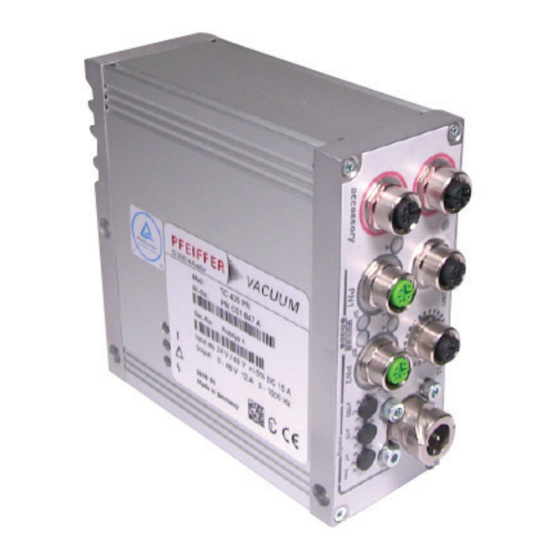
- Page 1 OPERATING INSTRUCTIONS Translation of the Original TC 400 PN Electronic drive unit...
-
Page 2: Telegram Example
Dear Customer, Thank you for choosing a Pfeiffer Vacuum product. Your new turbopump is designed to support you by its performance, its perfect operation and without interfering your individual application. The name Pfeiffer Vacuum stands for high-quality vacuum technology, a comprehensive and complete range of top-quality products and first-class service. -
Page 3: Table Of Contents
5.1.6 Acyclic data 5.1.7 Data types Interface RS-485 5.2.1 Connection options 5.2.2 Cross-linking via the RS-485 connection Pfeiffer Vacuum protocol for RS-485 interface 5.3.1 Telegram frame 5.3.2 Telegram description 5.3.3 Telegram example 1 5.3.4 Telegram example 2 5.3.5 Data types... - Page 4 Table of contents Operation Configuring the connections with the Pfeiffer Vacuum parameter set 7.1.1 Configuring the accessory connections 7.1.2 Select interfaces Operating modes 7.2.1 Gas type-dependent operation 7.2.2 Set value power consumption 7.2.3 Run-up time 7.2.4 Rotation speed switch points 7.2.5 Rotation speed setting mode...
- Page 5 List of tables List of tables Tbl. 1: Stickers on the product Tbl. 2: Abbreviations used in this document Tbl. 3: Permissible ambient conditions Tbl. 4: Data for use in safety-related applications in accordance with IEC 61508 and IEC 62061 Tbl.
- Page 6 List of figures List of figures Fig. 1: Connection panel TC 400 PN Fig. 2: Diagram and assignments of the connection panel Fig. 3: Connection options via interface RS-485 Fig. 4: Cross-linking of turbopumps with integrated electronic drive unit via interface RS-485 Fig.
-
Page 7: About This Manual
Keep the manual for future consultation. 1.1 Validity This operating instructions is a customer document of Pfeiffer Vacuum. The operating instructions de- scribe the functions of the named product and provide the most important information for the safe use of the device. The description is written in accordance with the valid directives. The information in this op- erating instructions refers to the product's current development status. -
Page 8: Stickers On The Product
Ampere Interrupting Capacity Profinet status LED (Bus Fault) Direct current Discovery and basic Configuration Protocol (Profinet protocol) Display Control Unit from Pfeiffer Vacuum DI/DO Digital input/digital output Rotation speed value of a vacuum pump (frequency, in rpm or Hz) XML-based Profinet file with description of a device provided by the device manufac-... -
Page 9: Trademark Proof
About this manual Abbreviation Meaning in this document Profinet status LED (System Fault) Time Temperature Electronic drive unit (turbo controller) Turbomolecular pump Temperature management system Electric voltage Extensible Markup Language Tbl. 2: Abbreviations used in this document 1.5 Trademark proof ● Profibus ®... -
Page 10: Safety
Safety 2 Safety 2.1 General safety information The following 4 risk levels and 1 information level are taken into account in this document. DANGER Immediately pending danger Indicates an immediately pending danger that will result in death or serious injury if not observed. ►... -
Page 11: Safety Precautions
Safety DANGER Danger to life from electric shock When establishing the voltages that exceed the specified safety extra-low voltage (according to IEC 60449 and VDE 0100), the insulating measures will be destroyed. There is a danger to life from elec- tric shock at the communication interfaces. -
Page 12: Limits Of Use Of The Product
2.5 Proper use ● The electronic drive unit is used exclusively for the operation of Pfeiffer Vacuum turbopumps and their accessories in a Process Field Network (Profinet). 2.6 Foreseeable improper use Improper use of the product invalidates all warranty and liability claims. -
Page 13: Tbl. 5: Data For Use In Safety-Related Applications In Accordance With
Safety Characteristics in accordance with EN ISO 13849-1 Characteristic Performance Level Category MTTF Average diagnostic coverage DC Value PL d Cat. 3 high (135 a) Medium (90 % - < 99 %) Tbl. 5: Data for use in safety-related applications in accordance with EN ISO 13849-1 ●... -
Page 14: Product Description
ID no. 000021320. 3.2 Product features The type TC 400 PN electronic drive unit is a fixed component of the turbopump. The purpose of the electronic drive unit is to drive, monitor and control the entire turbopump. Feature... -
Page 15: Connections
Pfeiffer Vacuum service purposes. RS-485 M12 bushing with screw lock for the connection of Pfeiffer Vacuum control panels or PC. The use of a Y-distributor permits the integration into a bus system. 2 × M12 bushings with threaded coupling and 2 LEDs for the connection of a Profi- net. -
Page 16: Installation
Installation 4 Installation 4.1 Connection diagram DANGER Danger to life from electric shock Power supply packs that are not specified or are not approved will lead to severe injury to death. ► Make sure that the power supply pack meets the requirements for double isolation between mains input voltage and output voltage, in accordance with IEC 61010-1 IEC 60950-1 and IEC 62368-1. -
Page 17: Profinet" Connection
Installation n.c. n.c. Zubehör A2 Zubehör B2 24 V DC** 24 V DC** Zubehör A1 Zubehör B1 CAN-H 24 V DC** GND*** CAN-L n.c. RS 485 D+ 24 V DC* out GND* RS 485 D- n.c. n.c. +U (+24/+48 V DC ±10%) Fig. -
Page 18: Interfaces
Interfaces 5 Interfaces 5.1 Profinet interface 5.1.1 Making connections The turbopump can be integrated in a Profinet bus system using the connections designated "PN1" and "PN2" on the electronic drive unit. The interface is galvanically safe and is isolated from the maximum supply voltage for the electronic drive unit. 5.1.2 Defining device ID Assign device name and IP address ►... -
Page 19: Tbl. 10: Speed Controlled Tmp Assembly: Output Data (Plc To Tc)
Interfaces Byte Name Meaning purge_valve_req Sealing gas valve pre-selection (0: closed, 1: enabled) 2–3 speed_setpoint Set rotation speed in rotation speed setting mode (Hz, Un- signed16) Tbl. 10: Speed Controlled TMP assembly: Output data (PLC to TC) Byte Name Meaning at_standby_speed At standby speed (0: no, 1: yes) at_rated_speed... -
Page 20: Tbl. 16: Bearingtemp: Input Data (Tc To Plc)
Interfaces Byte Name Meaning 0–3 value Measured value (Float32) status Status of measured value (Unsigned8) 11h: ok, 21h: uncertain, 31h: poor Tbl. 16: BearingTemp: Input data (TC to PLC) Byte Name Meaning 0–3 value Measured value (Float32) status Status of measured value (Unsigned8) 11h: ok, 21h: uncertain, 31h: poor Tbl. -
Page 21: Parameterization
Interfaces Byte Field Response Parameter number Parameter value 0: none 2: ok Parameter number (Unsigned32) value 7: Error Parameter number (Unsigned32) code 8: Error Parameter number 11: ok Parameter number (Float32) value Tbl. 22: PrmChannel: Input data (TC to PLC) Example: Reading operating hours for pump 1. -
Page 22: Acyclic Data
Profinet data types 5.2 Interface RS-485 The interface designated “RS-485” is intended for connecting a Pfeiffer Vacuum control unit or an exter- nal PC. The connections are galvanically safe and are isolated from the maximum supply voltage for the electronic drive unit. The electrical connections are optically decoupled internally. -
Page 23: Connection Options
RS-485 interface connection 3 Electronic drive unit Connecting Pfeiffer Vacuum control units or a PC One external control unit each can be connected at the RS-485 interface. 1. Use the respective connection cable from the control unit shipment or from the accessories pro- gram. -
Page 24: Pfeiffer Vacuum Protocol For Rs-485 Interface
3. Connect all devices to the bus with RS-485 D+ and RS-485 D-. 5.3 Pfeiffer Vacuum protocol for RS-485 interface 5.3.1 Telegram frame The telegram frame of the Pfeiffer Vacuum protocol contains only ASCII code characters [32; 127], the exception being the end character of the telegram C . Basically, a host (e.g. -
Page 25: Telegram Description
Interfaces 5.3.2 Telegram description Data query --> Control command --> Data response / Control command understood --> Error message --> NO_DEF Parameter number n2–n0 no longer exists _RANGE Data dn–d0 outside the permissible range _LOGIC Logical access error 5.3.3 Telegram example 1 Data query Current rotation speed (parameter [P:309], device address: "123") -->... -
Page 26: Data Types
Interfaces 5.3.5 Data types Data type Description Length Example l1 – l0 boolean_old Logical value (false/true) 000000 is equivalent to false 111111 is equivalent to true u_integer Positive whole number 000000 to 999999 u_real Positive fixed point number 001571 corresponds with 15.71 string Any character string with 6 charac-... -
Page 27: Parameter Set
Each parameter has a three-digit number and a description. The parameter can be accessed via Pfeiffer Vacuum control units or externally via RS-485 using Pfeiffer Vacuum protocol. The vacuum pump starts in standard mode with factory default pre-set parameters. - Page 28 Parameter set Display Description Functions Data Unit min. max. type cess fault type Cfg DO2 Output DO2 0 = Rotation speed switch configuration point reached 1 = No error 2 = Error 3 = Warning 4 = Error and/or warning 5 = Set rotation speed reached 6 = Pump on 7 = Pump accelerating...
- Page 29 Parameter set Display Description Functions Data Unit min. max. type cess fault type Cfg Acc A1 Configuration 0 = fan accessory 1 = Venting valve, closed with- connection out current 2 = Heating 3 = Backing pump 4 = Fan (temperature control- led) 5 = Sealing gas 6 = Always "0"...
-
Page 30: Status Requests
Parameter set Display Description Functions Data Unit min. max. type cess fault type CtrlViaInt Control via 1 = remote interface 2 = RS-485 4 = PV.can 8 = Fieldbus 16 = E74 255 = Unlock interface selec- tion IntSelLckd Interface se- 0 = off lection locked 1 = on... -
Page 31: Set Value Settings
Parameter set Display Description Func- Data Access Unit min. max. tions type type fault Nominal Spd Nominal rotational speed 999999 (Hz) DrvPower Drive power 999999 PumpCycles Pump cycles 65535 TempElec Temperature electronics °C 999999 TempPmpBot Temperature pump bottom °C 999999 part AccelDecel Acceleration/deceleration... -
Page 32: Additional Parameters For The Control Unit
The basic parameter set is set in the electronic drive unit ex-factory. For controlling con- nected external components (e.g. vacuum measuring equipment), additional parameters (extended parameter set) are available in the corresponding Pfeiffer Vacuum control units. ● Refer to the corresponding operating instructions of the respective components. -
Page 33: Operation
● The use of other accessories for turbopumps is possible and requires settings in the configuration of the electronic drive unit. ● The desired accessory output is configured via RS-485 using Pfeiffer Vacuum control units or a PC. ● For detailed information see the “Electronic drive unit TC 400” or “Electronic drive unit TC 700”... -
Page 34: Select Interfaces
► Make sure that the gas mode is set correctly by [P:027] in the electronic drive unit. ► Consult Pfeiffer Vacuum before you use gases with higher molecular masses (> 80). High gas throughput and high rotation speed lead to strong friction heating of the rotor. To avoid over- heating, power to rotation speed characteristics are implemented in the electronic drive unit. -
Page 35: Set Value Power Consumption
Operation P max [P:708] Fig. 5: Schematic diagram of power characteristics, example of heavy gases [P:027] = 0 Power consumption Power characteristic in gas mode "0" (gases with molecu- lar mass > 39, e.g. Argon) Rotation speed Power characteristic in gas mode "1" (gases with molecu- lar mass ≤... -
Page 36: Fig. 6: Rotation Speed Switch Point 1 Active
Operation Rotation speed switch point 1 [P:017] = 0 f (%) [P:701] [P:010] [P:302] Process Fig. 6: Rotation speed switch point 1 active Adjusting rotation speed switch point 1 Signal output and status parameters are based on the set value for the rotation speed switch point 1 [P:701]. -
Page 37: Rotation Speed Setting Mode
3. Check the set rotation speed (parameter [P:308] or [P:397]). 7.2.6 Standby Pfeiffer Vacuum recommends standby mode for the turbopump during process and production stops. When standby mode is active, the electronic drive unit reduces the rotation speed of the turbo pump. -
Page 38: Backing Pump Operating Modes
Fluctuations in the power consumption of idling turbopumps and varying fore-vac- uum pressures of the backing pumps require individual settings of the interval operation. Pfeiffer Vacuum recommends interval operation between 5 and 10 hPa. A pressure gauge and a dosing valve are required to set the switching thresholds. -
Page 39: Backing Pump Standby Mode
2. Use this signal for the control of a fore-vacuum safety valve. 7.2.9 Backing pump standby mode In case you are using a Pfeiffer Vacuum backing pump with rotation speed control, this can be used in standby mode by configuring the digital output [P:019] or [P:024]. The power consumption of the turbo- pump has a direct influence on the rotation speed of the backing pump. -
Page 40: 11Venting Modes
Operation Configuring the bottom part heating The accessory output controls the heating cartridges that maintain the bottom part of the turbopump at maximum temperature. The control is carried out according to pump-specific requirements, depending on the current power input of the vacuum pump and the switch point. 1. -
Page 41: Operation Monitoring
7.5.1 Operating mode display via LED LEDs on the electronic drive unit show the basic operating states of the vacuum pump. A differentiated error and warning display is only possible for operation with the Pfeiffer Vacuum display and control unit or a PC. - Page 42 Operation mutably stored in the electronic drive unit. For information purposes, various status requests are set up in the parameter set. ● In order to avoid switching off the turbopump, the electronic drive unit already reduces the power consumption in case of exceeding the warning threshold for excess temperature. ─...
-
Page 43: Recycling And Disposal
● Help to reduce the wastage of natural resources. ● Prevent contamination. 8.1 General disposal information Pfeiffer Vacuum products contain materials that you must recycle. ► Dispose of our products according to the following: – Iron – Aluminium –... -
Page 44: Malfunctions
Warnings (* Warning F –––– *) do not cause components to be switched off. Handling malfunction messages 1. Read out error codes via Pfeiffer Vacuum control units or a PC. 2. Remove the cause of the malfunction. 3. Reset the malfunction message with parameter [P:009]. - Page 45 Malfunctions Error Problem Possible causes Remedy code Err043 Internal configuration er- ● Device defective ● Contact Pfeiffer Vacuum Service Err044 Excess temperature, ● Insufficient cooling ● Improve the cooling electronics ● Check the operating conditions Err045 Excess temperature, ● Insufficient cooling ●...
- Page 46 Problem Possible causes Remedy code Err800 Magnetic bearing over- ● Impacts, vibrations ● Contact Pfeiffer Vacuum Service flow ● Device defective ● Check the operating conditions ● Only acknowledge for rotational speed f = 0 Err802 Magnetic bearing sen- ● Calibration values invalid ●...
-
Page 47: Warning And Malfunction Messages When Operating With Control Units
● Check the operating conditions ● Impermissible thermal radiation ● Impermissible magnetic field Wrn113 Inaccurate rotor tem- ● Internal communication error ● Contact Pfeiffer Vacuum Service perature Wrn115 Pump lower part tem- ● Device defective ● Contact Pfeiffer Vacuum Service... -
Page 48: Service Solutions By Pfeiffer Vacuum
We are always focused on perfecting our core competence – servicing of vacuum components. Once you have purchased a product from Pfeiffer Vacuum, our service is far from over. This is often exactly where service begins. Obviously, in proven Pfeiffer Vacuum quality. - Page 49 Service solutions by Pfeiffer Vacuum 5. Prepare the product for transport in accordance with the provisions in the contamination declaration. a) Neutralize the product with nitrogen or dry air. b) Seal all openings with blind flanges, so that they are airtight.
-
Page 50: Ec Declaration Of Conformity
This declaration of conformity has been issued under the sole responsibility of the manufac- turer. Declaration for product(s) of the type: Electronic drive unit TC 400 PN We hereby declare that the listed product satisfies all relevant provisions of the following European Directives. Low voltage 2014/35/EC... -
Page 51: Declaration Of Conformity
Semi F47-0200 EN IEC 61326-1:2021 Semi S2-0706 The manufacturer's authorized representative in the United Kingdom and the authorized agent for compiling the technical documentation is Pfeiffer Vacuum Ltd, 16 Plover Close, In- terchange Park, MK169PS Newport Pagnell. Signature: Pfeiffer Vacuum GmbH Berliner Straße 43...
Need help?
Do you have a question about the TC 400 PN and is the answer not in the manual?
Questions and answers