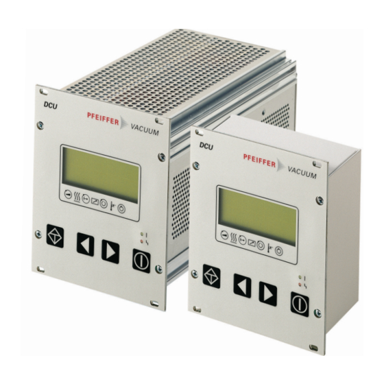
Pfeiffer Vacuum DCU 002 Operating Instructions Manual
Display control unit
Hide thumbs
Also See for DCU 002:
- Operating instructions manual (22 pages) ,
- Operating instructions manual (36 pages)

Subscribe to Our Youtube Channel
Related Manuals for Pfeiffer Vacuum DCU 002


Summary of Contents for Pfeiffer Vacuum DCU 002
- Page 1 OPERATING INSTRUCTIONS Translation of the Original DCU 002 I 110 | 180 | 310 | 400 Display Control Unit...
- Page 2 Customer, Thank you for choosing a Pfeiffer Vacuum product. Your new Display Control Unit should support you in your individual application with full performance and without malfunctions. The name Pfeiffer Vacuum stands for high-quality vacuum technology, a comprehensive and complete range of top-quality products and first-class service. From this extensive, practical experience we have gained a large volume of information that can contribute to efficient deployment and to your personal safety.
-
Page 3: Table Of Contents
Table of contents Table of contents About this manual Validity 1.1.1 Applicable documents 1.1.2 Variants Target group Conventions 1.3.1 Instructions in the text 1.3.2 Pictographs 1.3.3 Stickers on the product 1.3.4 Abbreviations Safety General safety instructions Safety instructions Safety precautions Limits of use of the product Proper use Foreseeable misuse... - Page 4 Table of contents Service solutions from Pfeiffer Vacuum Accessories Technical data and dimensions 11.1 Technical data 11.2 Dimension drawings Declaration of conformity 4/38...
- Page 5 Status symbols and display on the DCU..............17 Tbl. 7: Connection possibilities for electronic drive unit and transmitter......19 Tbl. 8: Available Pfeiffer Vacuum transmitters for connection to a DCU......22 Tbl. 9: Explanation and meaning of the parameters............23 Tbl. 10: Parameter for DCU functions................... 24 Tbl.
- Page 6 Connection of the grounding cable to the DCU with integrated power supply pack..Fig. 8: Example: Connection of a DCU 002 to a vacuum pump.......... 21 Fig. 9: Example: Connection of a DCU with integrated power supply pack to a vacuum pump.........................21...
-
Page 7: About This Manual
Keep the manual for future consultation. 1.1 Validity These operating instructions are for customers of Pfeiffer Vacuum. They describe the function of the designated product and provide the most important information for safe usage of the product. The de- scriptions comply with applicable directives. All information provided in these operating instructions refer to the current development status of the product. -
Page 8: Pictographs
About this manual 1.3.2 Pictographs Pictographs used in the document indicate useful information. Note 1.3.3 Stickers on the product This section describes all the stickers on the product along with their meaning. Rating plate (example) Rating plates of the devices are affixed to the housing where they Mod.: Ser. -
Page 9: Tbl. 2: Abbreviations Used In This Document
Piezo/Pirani transmitter RP Switch on power supply pack Temperature (in °C) Turbopump electronic drive unit (turbo controller) Pirani transmitter Power supply pack, voltage supply (turbo power supply) Connecting socket for a Pfeiffer Vacuum transmitter Tbl. 2: Abbreviations used in this document 9/38... -
Page 10: Safety
Safety 2 Safety 2.1 General safety instructions This document includes the following four risk levels and one information level. DANGER Imminent danger Indicates a hazardous situation which, if not avoided, will result in death or serious injury. ► Instructions on avoiding the hazardous situation WARNING Possibly imminent danger Indicates a hazardous situation which, if not avoided, could result in death or serious injury. - Page 11 Safety DANGER Danger to life from electric shock Power supply packs that are not specified or are not approved will lead to severest injuries up to death. ► Make sure that the power supply pack meets the requirements for double isolation between mains input voltage and output voltage, in accordance with IEC 61010 and IEC 60950.
-
Page 12: Safety Precautions
● The DCU Display Control Units are used exclusively for control of the electronic drive units for Pfeiffer Vacuum vacuum pumps and their accessories. ● The version with integrated power supply pack also supplies the operating voltage for the vacuum pump. - Page 13 Safety ● Operation in explosion-hazard areas ● Use of accessories or spare parts that are not listed in these instructions 13/38...
-
Page 14: Product Description
● Operating manual 3.4 Function The DCU is a display and control unit for Pfeiffer Vacuum vacuum pumps with integrated electronic drive unit. This device provides an overview of all control parameters for the electronic drive unit. It is also possible to connect a pressure-measuring tube. -
Page 15: Key Functions
Mains switch S1 Connecting socket RS-485 Earthed conductor, M4 Contrast setting Mounting bracket for mains connection RS485 Fig. 4: DCU 002, rear view Front plate, rear side Connecting socket RS-485 Mounting hole Contrast setting Connecting socket X3 3.4.1 Key functions 4 short-stroke keys (softkeys) make up the user interface of the DCU. -
Page 16: Status Symbols
Product description Parameter | use Description corresponds to Pumping station ON/OFF: All components are put [010] = 0 or 1 into/out of operation according to their configuration Error acknowledgement (Reset): Resets active malfunc- tion messages in case the cause is eliminated. [308] -->... -
Page 17: Tbl. 6: Status Symbols And Display On The Dcu
Product description Tbl. 6: Status symbols and display on the DCU 17/38... -
Page 18: Installation
Installation 4 Installation 4.1 Preparing for installation General comments regarding installation ► Choose a site for installation where access to the product and to supply lines is possible at all times. ► Respect the ambient conditions stated for the area of use. ►... -
Page 19: Connection Diagram
DCU 400 Fig. 5: Connection diagram for the DCU with integrated power supply pack RS485 RS485 DCU 002 Fig. 6: Connection diagram for the DCU 002 Connection to: DCU 002 DCU with integrated power supply pack TC 110 TC 110... -
Page 20: Earthing The Device
4.3.2 Earthing the device ● The ground terminal is obligatory for DCUs with integrated power supply pack. ● Pfeiffer Vacuum recommends connecting a suitable grounding cable to the DCU 002 to discharge applicative interferences. ● Alternatively, the DCU 002 is grounded following installation in a rack. -
Page 21: Fig. 8: Example: Connection Of A Dcu 002 To A Vacuum Pump
Connecting the DCU 002 The DCU 002 receives the supply voltage via the electronic drive unit interface. The RS485 serial inter- face of the DCU is used exclusively to control the electronic drive unit of a vacuum pump. The interface protocol us described in the operating manual of the respective electronic drive unit. -
Page 22: Establishing Mains Connection
4.3.4 Establishing mains connection Only applicable for configurations with integrated power supply pack (DCU 110, DCU 180, DCU 310 and DCU 400). The DCU 002 receives the supply voltage via the electronic drive unit RS-485 interface. Establishing mains connection for DCU 1. -
Page 23: Parameter Set
Important settings and function-related variables are factory-programmed into the electronic drive unit as parameters. Each parameter has a three-digit number and a description. The use of the parameter is possible via Pfeiffer Vacuum displays and control panels, or externally via RS-485 using Pfeiffer Vac- uum protocol. -
Page 24: Data Types Used
Parameter set Display Designations Functions Data Access Unit min. max. type type fault Param set Parameter set 0 = Basic pa- rameter set 1 = Extended parameter set Servicelin Insert service line Tbl. 10: Parameter for DCU functions 5.3 Data types used Data type Description Length l1 –... -
Page 25: Operation
Switching on the current supply at the DCU with integrated power supply pack ► Switch on the current supply with the S1 switch on the DCU. Switching on the current supply at the DCU 002 ► Switch on the current supply via the voltage supply for the vacuum pump. -
Page 26: Displaying And Configuring Parameters With The Dcu
Operation Test Function LC-display All characters in the LC display go dark for a short time. The red and green LEDs illuminate during the self-test. Hardware – Connection to the electronic drive Request regarding correct connection to the electronic drive unit unit Parameter check The DCU loads the parameter set from the electronic drive unit... -
Page 27: Switching On The Connected Vacuum Pump
Pressure measurement with the DCU The DCU provides an approximate pressure reading. For the precise pressure measurement, and in particular for linear transmitters in the lower pressure range, Pfeiffer Vacuum measuring instruments are ideal. Displaying active transmitters The DCU detects transmitters with the same image incidences group. -
Page 28: Operating Mode Display Via Led
6.8 Switching off the DCU Switching off DCU 002 The power supply pack connected for the vacuum pump supplies the DCU 002 with operating voltage via the electronic drive unit. 1. Disconnect the voltage supply at the power supply pack of the vacuum pump. -
Page 29: Maintenance
Maintenance 7 Maintenance WARNING Danger to life from electric shock during maintenance and service work The device is only completely de-energized when the mains plug has been disconnected and the vacuum pump is at a standstill. There is a danger to life from electric shock when making contact with live components. -
Page 30: Malfunctions
● Replace the pressure gauge com- pletely ** Error E040 ** Hardware error ● external RAM faulty ● Contact Pfeiffer Vacuum Service. ● EPROM checksum incorrect ● Contact Pfeiffer Vacuum Service. ** Error E042 ** Hardware error ** Error E043 ** Hardware error ●... -
Page 31: Service Solutions From Pfeiffer Vacuum
We are consistently striving to perfect our core competence, service for vacuum components. And our service is far from over once you’ve purchased a product from Pfeiffer Vacuum. It often enough really just begins then. In proven Pfeiffer Vacuum quality, of course. - Page 32 ERKLÄRUNG KONTAMINIERUNG Then send your product to your local Service Center. You will receive a confirmation message/a quotation from Pfeiffer Vacuum. For all service orders, our General Terms and Conditions of Sales and Supply General Terms and Conditions of Repair and Maintenance apply to vacuum equipment and components.
-
Page 33: Accessories
Accessories 10 Accessories Please refer to the accessories list for the individual components in their respective operating manual or online at pfeiffer-vacuum.de. 33/38... -
Page 34: Technical Data And Dimensions
Technical data and dimensions 11 Technical data and dimensions 11.1 Technical data Selection field DCU 002, Display Control Unit Order number PM 061 348 -T Connection 12 – 30 V DC Power consumption 5 VA Protection category IP20 Ambient temperature 5 – 50 °C Weight 0.4 kg... -
Page 35: Fig. 11: Dimensions Dcu 002
Technical data and dimensions 64.5 106.4 91.5 52.5 Fig. 11: Dimensions DCU 002 29.5 29.7 106.5 91.5 29.7 75.35 104.8 Fig. 12: Dimensions DCU 110 106.5 29.5 29.7 91.5 29.7 75.35 104.8 Fig. 13: Dimensions DCU 180, DCU 310, DCU 400... -
Page 36: Declaration Of Conformity
● Electromagnetic compatibility 2014/30/EU ● Low voltage 2014/35/EC ● Restriction of the use of certain hazardous substances 2011/65/EU DCU 002 DCU 110 | DCU 180 | DCU 310 | DCU 400 Harmonized standards and applied national standards and specifications: DIN EN 61000-3-2: 2014... - Page 37 37/38...
Need help?
Do you have a question about the DCU 002 and is the answer not in the manual?
Questions and answers