Pfeiffer Vacuum DCU 002 Operating Instructions Manual
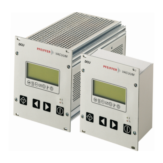
Display control unit
Hide thumbs
Also See for DCU 002:
- Operating instructions manual (22 pages) ,
- Operating instructions manual (38 pages)

Related Manuals for Pfeiffer Vacuum DCU 002


Summary of Contents for Pfeiffer Vacuum DCU 002
- Page 1 OPERATING INSTRUCTIONS Translation of the Original DCU 002 I 110 | 180 | 310 | 400 Display Control Unit...
- Page 2 Dear Customer, Thank you for choosing a Pfeiffer Vacuum product. Your new Display Control Unit should support you in your individual application with full performance and without malfunctions. The name Pfeiffer Vacuum stands for high-quality vacuum technology, a comprehensive and complete range of top-quality products and first-class service.
-
Page 3: Table Of Contents
Table of contents Table of contents About this manual Validity 1.1.1 Applicable documents 1.1.2 Variants Target group Conventions 1.3.1 Instructions in the text 1.3.2 Pictographs 1.3.3 Stickers on the product 1.3.4 Abbreviations Safety General safety information Safety instructions Safety precautions Limits of use of the product Proper use Foreseeable improper use... - Page 4 Table of contents General Error codes Service solutions by Pfeiffer Vacuum Accessories Technical data and dimensions 11.1 Technical data 11.2 Dimension drawings Declaration of Conformity 4/36...
- Page 5 Tbl. 6: Status symbols and display Tbl. 7: Connection possibilities for electronic drive unit and transmitter Tbl. 8: Available Pfeiffer Vacuum transmitters for connection to a DCU Tbl. 9: Explanation and meaning of the parameters Tbl. 10: Parameter for DCU functions Tbl.
- Page 6 Connection of the grounding cable to the DCU with integrated power supply pack Fig. 8: Example: Connection of a DCU 002 to a vacuum pump Fig. 9: Example: Connection of a DCU with integrated power supply pack to a vac- uum pump Fig.
-
Page 7: About This Manual
Keep the manual for future consultation. 1.1 Validity This operating instructions is a customer document of Pfeiffer Vacuum. The operating instructions de- scribe the functions of the named product and provide the most important information for the safe use of the device. The description is written in accordance with the valid directives. The information in this op- erating instructions refers to the product's current development status. -
Page 8: Stickers On The Product
About this manual Note 1.3.3 Stickers on the product This section describes all the stickers on the product along with their meaning. Rating plate (example) Rating plates of the devices are affixed to the housing where D-35614 Asslar they can be clearly seen Mod.: DCU 110 Ser. -
Page 9: Tbl. 2: Abbreviations Used In This Document
Piezo/Pirani transmitter RP Switch on power supply pack Temperature (in °C) Turbopump electronic drive unit (turbo controller) Pirani transmitter Power supply pack, voltage supply (turbo power supply) Connecting socket for a Pfeiffer Vacuum transmitter Tbl. 2: Abbreviations used in this document 9/36... -
Page 10: Safety
Safety 2 Safety 2.1 General safety information The following 4 risk levels and 1 information level are taken into account in this document. DANGER Immediately pending danger Indicates an immediately pending danger that will result in death or serious injury if not observed. ►... - Page 11 Safety DANGER Danger to life from electric shock Power supply packs that are not specified or are not approved will lead to severe injury to death. ► Make sure that the power supply pack meets the requirements for double isolation between mains input voltage and output voltage, in accordance with IEC 61010-1 IEC 60950-1 and IEC 62368-1.
-
Page 12: Safety Precautions
● The DCU Display Control Units are used exclusively for control of the electronic drive units for Pfeiffer Vacuum vacuum pumps and their accessories. ● The version with integrated power supply pack also supplies the operating voltage for the vacuum pump. - Page 13 Safety ● Use in areas with ionizing radiation ● Operation in potentially explosive areas ● Use of accessories or spare parts that are not listed in these instructions 13/36...
-
Page 14: Product Description
● Operating manual 3.4 Function The DCU is a display and control unit for Pfeiffer Vacuum vacuum pumps with integrated electronic drive unit. This device provides an overview of all control parameters for the electronic drive unit. It is also possible to connect a pressure-measuring tube. -
Page 15: Key Functions
4 Connecting socket RS-485 Earthed conductor, M4 5 Contrast setting Mounting bracket for mains connection RS485 Fig. 4: DCU 002, rear view 1 Front plate, rear side Connecting socket RS-485 2 Mounting hole Contrast setting 3 Connecting socket X3 3.4.1 Key functions Four short-stroke keys (softkeys) make up the user interface. -
Page 16: Status Symbols
Product description Parameter | Application Explanation Equivalent to Pumping station on/off: Starts/shuts down all compo- [010] = 0 or 1 nents according to their configuration Malfunction acknowledgment (reset): Resets active er- ror messages, provided that the cause has been rectified. [308] -->... -
Page 17: Installation
Installation 4 Installation 4.1 Preparing for installation General comments regarding installation ► Choose a site for installation where access to the product and to supply lines is possible at all times. ► Install the device upright. ► Respect the ambient conditions stated for the area of use. ►... -
Page 18: Connection Diagram
Fig. 5: Connection diagram for the DCU with integrated power supply pack RS485 RS485 DCU 002 Fig. 6: Connection diagram for the DCU 002 Connection to: DCU 002 DCU with integrated power supply pack TC 110 TC 110 Vacuum pump with electronic... -
Page 19: Earthing The Device
4.3.2 Earthing the device ● The ground terminal is obligatory for DCUs with integrated power supply pack. ● Pfeiffer Vacuum recommends connecting a suitable grounding cable to the DCU 002 to discharge applicative interferences. ● Alternatively, the DCU 002 is grounded following installation in a rack. -
Page 20: Establishing Mains Connection
Connecting the DCU 002 The DCU 002 receives the supply voltage via the electronic drive unit interface. The RS485 serial inter- face of the DCU is used exclusively to control the electronic drive unit of a vacuum pump. The interface protocol us described in the operating manual of the respective electronic drive unit. -
Page 21: Connecting Measuring Tubes
4. Secure the connection with the mounting bracket. 5. Connect the mains cable to the mains power supply on the customer-side. 4.4 Connecting measuring tubes The connecting socket with designation "X3" is used to connect a Pfeiffer Vacuum transmitter. Measuring tubes Display on the DCU [P:738]... -
Page 22: Parameter Set
Important settings and function-related characteristics are factory-programmed into the electronic drive unit as parameters. Each parameter has a three-digit number and a description. The use of the parame- ter is possible via Pfeiffer Vacuum displays and control panels, or externally via RS-485 using Pfeiffer Vacuum protocol. -
Page 23: Data Types
Parameter set 5.3 Data types Data type Description Length Example l1 – l0 boolean_old Logical value (false/true) 000000 is equivalent to false 111111 is equivalent to true u_integer Positive whole number 000000 to 999999 u_real Positive fixed point number 001571 corresponds with 15.71 string Any character string with 6 charac-... -
Page 24: Operation
Switching on the current supply at the DCU with integrated power supply pack ► Switch on the current supply with the S1 switch on the DCU. Switching on the current supply at the DCU 002 ► Switch on the current supply via the voltage supply for the vacuum pump. -
Page 25: Displaying And Configuring Parameters
Operation Test Function Connection to the electronic drive Request regarding correct connection to the electronic drive unit unit Parameter check The DCU loads the parameter set from the electronic drive unit Identification of the connected de- ● Electronic drive unit designation display, vices ●... -
Page 26: Transmitter Operation
6.5 Transmitter operation Pressure measurement with the DCU The DCU provides an approximate pressure reading. For the precise pressure measure- ment, and in particular for linear transmitters in the lower pressure range, Pfeiffer Vacuum measuring instruments are ideal. Displaying active transmitters The DCU detects transmitters with the same image incidences group. -
Page 27: Switching Off The Dcu
6.8 Switching off the DCU Switching off DCU 002 The power supply pack connected for the vacuum pump supplies the DCU 002 with operating voltage via the electronic drive unit. 1. Disconnect the voltage supply at the power supply pack of the vacuum pump. -
Page 28: Maintenance
Maintenance 7 Maintenance WARNING Danger to life from electric shock during maintenance and service work The device is only completely de-energized when the mains plug has been disconnected and the vacuum pump is at a standstill. There is a danger to life from electric shock when making contact with live components. -
Page 29: Malfunctions
1. Read out error codes via Pfeiffer display and control units or a PC. 2. Remove the cause of the malfunction. 3. Reset the malfunction message with parameter [P:009]. – Use preconfigured quick keys with the symbol or display tiles on Pfeiffer Vacuum display and control units. Display in DCU Problem... -
Page 30: Service Solutions By Pfeiffer Vacuum
We are always focused on perfecting our core competence – servicing of vacuum components. Once you have purchased a product from Pfeiffer Vacuum, our service is far from over. This is often exactly where service begins. Obviously, in proven Pfeiffer Vacuum quality. - Page 31 Service solutions by Pfeiffer Vacuum 5. Prepare the product for transport in accordance with the provisions in the contamination declaration. a) Neutralize the product with nitrogen or dry air. b) Seal all openings with blind flanges, so that they are airtight.
-
Page 32: Accessories
Accessories 10 Accessories Please refer to the accessories list for the individual components in their respective operat- ing manual or online at pfeiffer-vacuum.de. 32/36... -
Page 33: Technical Data And Dimensions
Technical data and dimensions 11 Technical data and dimensions 11.1 Technical data Selection field DCU 002, Display control unit Part number PM 061 348 AT Connection 12 – 30 V DC Power consumption 5 VA Protection degree IP20 Ambient temperature 5 – 50 °C Weight 0.4 kg... - Page 34 Technical data and dimensions 64.5 106.4 91.5 52.5 Fig. 11: Dimensions DCU 002 29.5 29.7 106.5 91.5 29.7 75.35 104.8 Fig. 12: Dimensions DCU 110 106.5 29.5 29.7 91.5 29.7 75.35 104.8 Fig. 13: Dimensions DCU 180, DCU 310, DCU 400...
-
Page 35: Declaration Of Conformity
Declaration of Conformity Declaration for product(s) of the type: Display Control Unit DCU 002 DCU 110 | DCU 180 | DCU 310 | DCU 400 We hereby declare that the listed product satisfies all relevant provisions of the following European Directives.
Need help?
Do you have a question about the DCU 002 and is the answer not in the manual?
Questions and answers