
Subscribe to Our Youtube Channel
Related Manuals for GORMAN-RUPP 82D1-1B20 FT4-X


Summary of Contents for GORMAN-RUPP 82D1-1B20 FT4-X
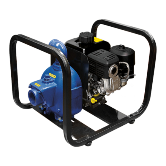
- Page 1 OM-06790-01 October 7, 2015 INSTALLATION, OPERATION, AND MAINTENANCE MANUAL WITH PARTS LIST 80 SERIES PUMP MODEL 82D1-1B20 FT4-X GORMAN‐RUPP PUMPS www.grpumps.com 2015 Gorman‐Rupp Pumps Printed in U.S.A.
- Page 2 Register your new Gorman‐Rupp pump online at www.grpumps.com Valid serial number and e‐mail address required. The engine exhaust from this product contains chemicals known to the State of California to cause cancer, birth defects or other reproductive harm. RECORD YOUR PUMP MODEL AND SERIAL NUMBER Please record your pump model and serial number in the spaces provided below.
-
Page 3: Table Of Contents
TABLE OF CONTENTS INTRODUCTION ..........PAGE I - 1 SAFETY ‐... - Page 4 TABLE OF CONTENTS (continued) Pump End Assy ............PAGE E - 5 PUMP AND SEAL DISASSEMBLY AND REASSEMBLY .
-
Page 5: Introduction
80 SERIES OM-06790 INTRODUCTION Thank You for purchasing a Gorman‐Rupp pump. HAZARD AND INSTRUCTION Read this manual carefully to learn how to safely DEFINITIONS install and operate your pump. Failure to do so could result in personal injury or damage to the The following are used to alert maintenance per... -
Page 6: Safety - Section A
80 SERIES OM-06790 SAFETY ‐ SECTION A This information applies to 80 Series en gine driven pumps. Refer to the manual accompanying the engine before at tempting to begin operation. Before attempting to open or service the pump: This manual will alert personnel to 1. - Page 7 OM-06790 80 SERIES of time. If operated against a closed dis When operating internal combustion charge valve, pump components will engines in an enclosed area, make cer deteriorate, and the liquid could come tain that exhaust fumes are piped to the to a boil, build pressure, and cause the outside.
-
Page 8: Installation - Section B
See Figure 1 for the approximate physical dimen configuration, and priming must be tailored to the sions of this pump. OUTLINE DRAWING Figure 1. Pump Model 82D1-1B20 FT4-X PREINSTALLATION INSPECTION a. Inspect the pump and engine for cracks, dents, damaged threads, and other obvious damage. -
Page 9: Positioning Pump
OM-06362 80 SERIES ing, check for loose hardware at mating sur Mounting faces. Locate the pump in an accessible place as close as practical to the liquid being pumped. Level mount c. Carefully read all tags, decals, and markings ing is essential for proper operation. on the pump assembly, and perform all duties indicated. -
Page 10: Gauges
80 SERIES OM-06790 place by tightening the flange bolts and/or cou If a strainer is not furnished with the pump, but is plings. installed by the pump user, make certain that the total area of the openings in the strainer is at least Lines near the pump must be independently sup... -
Page 11: Discharge Lines
OM-06362 80 SERIES recommended minimum submergence vs. veloc by installing a standard pipe increaser fitting at the ity. end of the suction line. The larger opening size will reduce the inlet velocity. Calculate the required submergence using the following formula based NOTE on the increased opening size (area or diameter). -
Page 12: Grounding
80 SERIES OM-06790 submerged. The line must be large enough to pre al Electrical Codes and all local codes. Be sure the vent clogging, but not so large as to affect pump clamp or fastener has made a tight electrical con discharge capacity. -
Page 13: Operation - Section C
OM-06790 80 SERIES OPERATION - SECTION C Review all SAFETY information in Section A. not prime when dry. Extended operation of a dry pump will destroy the seal assembly. Follow the instructions on all tags, labels and Add liquid to the pump casing when: decals attached to the pump. -
Page 14: Lines Without A Bypass
OM-06790 80 SERIES open the discharge throttling valve. Liquid will then gaged to be ejected with great force. al continue to circulate through the bypass line while low the pump to cool before servicing. the pump is in operation. Strainer Check Lines Without a Bypass If a suction strainer has been shipped with the pump or installed by the user, check the strainer... -
Page 15: Cold Weather Preservation
OM-06790 80 SERIES shock waves can be transmitted to the pump and Cold Weather Preservation piping system. Close all connecting valves slowly. In below freezing conditions, drain the pump to On engine driven pumps, reduce the throttle prevent damage from freezing. Also, clean out any speed slowly and allow the engine to idle briefly be... -
Page 16: Troubleshooting - Section D
80 SERIES OM-06790 TROUBLESHOOTING - SECTION D Review all SAFETY information in Section A. Before attempting to open or service the pump: 1. Familiarize yourself with this manual. 2. Shut down the engine and take pre cautions to ensure that the pump will remain inoperative. - Page 17 OM-06790 80 SERIES TROUBLE POSSIBLE CAUSE PROBABLE REMEDY Air leak in suction line. Correct leak. PUMP STOPS OR FAILS TO DELIVER Lining of suction hose collapsed. Replace suction hose. RATED FLOW OR Suction intake not submerged at Check installation and correct PRESSURE (cont.) proper level or sump too small.
- Page 18 80 SERIES OM-06790 equipped) between regularly scheduled inspec PREVENTIVE MAINTENANCE tions can indicate problems that can be corrected Since pump applications are seldom identical, and before system damage or catastrophic failure oc pump wear is directly affected by such things as curs.
-
Page 19: Pump Maintenance And Repair - Section E
OM-06790 PUMP MAINTENANCE AND REPAIR ‐ SECTION E MAINTENANCE AND REPAIR OF THE WEARING PARTS OF THE PUMP WILL MAINTAIN PEAK OPERATING PERFORMANCE. STANDARD PERFORMANCE FOR PUMP MODEL 82D1-1B20 FT4-X Based on 70 F (21 C) clear water (corrected to .80 specific gravity) at sea level with minimum suc... - Page 20 OM-06790 80 SERIES PARTS PAGE ILLUSTRATION Figure 1. Pump Model 82D1-1B20 FT4-X PAGE E - 2 MAINTENANCE & REPAIR...
-
Page 21: Parts Lists
80 SERIES OM-06790 PARTS LIST Pump Model 82D1-1B20 FT4-X (From S/N 1597804 Up) If your pump serial number is followed by an “N”, your pump is NOT a standard production model. Contact the Gorman‐Rupp Company to verify part numbers. ITEM... - Page 22 OM-06790 80 SERIES ILLUSTRATION Figure 2. Pump Parts Only 82D1-(1B20)-X PPO PAGE E - 4 MAINTENANCE & REPAIR...
- Page 23 80 SERIES OM-06790 PARTS LIST Pump Parts Only 82D1-(1B20)-X PPO ITEM PART NAME PART MAT'L ITEM PART NAME PART MAT'L NUMBER CODE NUMBER CODE PUMP CASING 6846C 13040 CASING DRAIN PLUG 15079 FILL PLUG ASSY 48271-062 ----- 1 FLAT WASHER KF04 18040 PIPE NIPPLE...
- Page 24 OM-06790 80 SERIES PUMP AND SEAL DISASSEMBLY nying the engine before attempting to start the engine. AND REASSEMBLY Review all SAFETY information in Section A. Follow the instructions on all tags, label and de cals attached to the pump. If this pump is used with volatile and/or flammable liquids, be certain proper This pump requires little service due to its rugged, safety practices are followed before op...
- Page 25 80 SERIES OM-06790 If no further disassembly is required, see Suction ing portion of the seal off the engine shaft as a unit. Check Valve Installation. Apply oil to the shaft sleeve and work it up under the rubber bellows. Slide the rotating portion of the seal off the shaft sleeve.
- Page 26 OM-06790 80 SERIES finished faces; even fingerprints on the faces can If a replacement seal is being used, remove it from shorten seal life. If necessary, clean the faces with a the container and inspect the precision finished non‐oil based solvent and a clean, lint‐free tissue. faces to ensure that they are free of any foreign Wipe lightly in a concentric pattern to avoid matter.
- Page 27 80 SERIES OM-06790 til fully seated. The O.D. of the pipe should be ap clearance can be obtained by adding or removing proximately the same as the O.D. of the seal spring. gaskets in the pump casing gasket set until the im peller scrapes against the wear plate when the shaft is turned.
- Page 28 OM-06790 80 SERIES Engine commercial model. It has been specially modified by Gorman‐Rupp for pumping gasoline and other Consult the literature supplied with the engine, or petroleum products in a well ventilated, non‐flam contact your local engine representative. mable atmosphere, free of combustible hazards. Further modifications may not be made without ENGINE MODIFICATIONS jeopardizing the integrity of the safety features.
- Page 29 For Warranty Information, Please Visit www.grpumps.com/warranty or call: U.S.: 419-755-1280 Canada: 519-631-2870 International: +1-419-755-1352 GORMAN‐RUPP PUMPS...
Need help?
Do you have a question about the 82D1-1B20 FT4-X and is the answer not in the manual?
Questions and answers