Table of Contents
Advertisement
Quick Links
OM-00766-01
ABCE
November 23, 1979
Rev. B 03-14-05
INSTALLATION, OPERATION,
AND MAINTENANCE MANUAL
WITH PARTS LIST
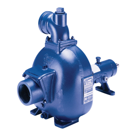
80 SERIES PUMP
MODEL
81 1/2E3−B
THE GORMAN-RUPP COMPANY D MANSFIELD, OHIO
www.gormanrupp.com
D
GORMAN-RUPP OF CANADA LIMITED
ST. THOMAS, ONTARIO, CANADA
Printed in U.S.A.
e
Copyright by the Gorman-Rupp Company
Advertisement
Table of Contents

Related Manuals for GORMAN-RUPP 811/2E3-B


Summary of Contents for GORMAN-RUPP 811/2E3-B
- Page 1 Rev. B 03-14-05 INSTALLATION, OPERATION, AND MAINTENANCE MANUAL WITH PARTS LIST 80 SERIES PUMP MODEL 81 1/2E3−B THE GORMAN-RUPP COMPANY D MANSFIELD, OHIO www.gormanrupp.com GORMAN-RUPP OF CANADA LIMITED ST. THOMAS, ONTARIO, CANADA Printed in U.S.A. Copyright by the Gorman-Rupp Company...
-
Page 2: Table Of Contents
TABLE OF CONTENTS INTRODUCTION ..........PAGE I −... - Page 3 TABLE OF CONTENTS (continued) PUMP MAINTENANCE AND REPAIR - SECTION E ....PAGE E − 1 PERFORMANCE CURVE ........... PAGE E −...
-
Page 4: Introduction
80 SERIES OM−00766 INTRODUCTION Thank You for purchasing a Gorman-Rupp pump. The following are used to alert maintenance per- Read this manual carefully to learn how to safely sonnel to procedures which require special atten- install and operate your pump. Failure to do so... -
Page 5: Safety - Section A
OM−00766 SAFETY - SECTION A This information applies to 80 Series ba- containing specified entrained solids. sic pumps. Gorman-Rupp has no con- Only the Gorman-Rupp Company or an trol over or particular knowledge of the authorized Gorman-Rupp distributor power source which will be used. Refer... - Page 6 OM−00766 80 SERIES of time. If operated against a closed dis- charge valve, pump components will deteriorate, and the liquid could come to a boil, build pressure, and cause the If this pump is used with volatile and/or pump casing to rupture or explode. flammable liquids, overheating may produce dangerous fumes.
-
Page 7: Installation − Section Bpage B
E, Page 1). Most of the information pertains to a standard For further assistance, contact your Gorman-Rupp static lift application where the pump is positioned distributor or the Gorman-Rupp Company. above the free level of liquid to be pumped. -
Page 8: Preinstallation Inspection
If the maximum shelf life has been exceeded, or if anything appears to be abnormal, contact your Pump performance is adversely effected by in- Gorman-Rupp distributor or the factory to deter- creased suction lift, discharge elevation, and fric- mine the repair or updating policy. Do not put the tion losses. -
Page 9: Materials
80 SERIES OM−00766 Materials the source of the liquid being pumped; if the line slopes down to the pump at any point along the suction run, air pockets will be created. Either pipe or hose maybe used for suction and discharge lines;... -
Page 10: Suction Line Positioning
OM−00766 80 SERIES If there is a liquid flow from an open pipe into the tance equal to at least 3 times the diameter of the sump, the flow should be kept away from the suc- suction pipe. tion inlet because the inflow will carry air down into the sump, and air entering the suction line will re- Suction Line Positioning duce pump efficiency. -
Page 11: Bypass Lines
NOTE Check Rotation, Section C, before final alignment of the pump. When mounted at the Gorman-Rupp factory, driver and pump are aligned before shipment. Misalign- ment will occur in transit and handling. Pumps Figure 3A. Aligning Spider Type Couplings INSTALLATION PAGE B −... -
Page 12: V-Belt Drives
OM−00766 80 SERIES MISALIGNED: MISALIGNED: ALIGNED: SHAFTS SHAFTS SHAFTS PARALLEL AND NOT PARALLEL NOT IN LINE SHEAVES IN LINE Figure 3C. Alignment of V-Belt Driven Pumps Tighten the belts in accordance with the belt manu- Figure 3B. Aligning Non-Spider Type Cou- plings facturer’s instructions. -
Page 13: Operation − Section C
Only the Gorman-Rupp Company or an authorized Gorman-Rupp distributor may modify a pump or approve its use for handling volatile, flammable liquids. If the pump is used for handling volatile,... -
Page 14: Starting
OM−00766 80 SERIES Lines Without a Bypass STARTING Open all valves in the discharge line and start the Consult the operations manual furnished with the engine. Priming is indicated by a positive reading power source. on the discharge pressure gauge or by a quieter operation. -
Page 15: Strainer Check
OM−00766 80 SERIES Strainer Check head, gradually close the discharge throttling valve before stopping the pump. If a suction strainer has been shipped with the After stopping the pump, lock out or disconnect pump or installed by the user, check the strainer the power source to ensure that the pump will re- regularly, and clean it as necessary. -
Page 16: Troubleshooting − Section D
80 SERIES OM−00766 TROUBLESHOOTING − SECTION D Review all SAFETY information in Section A. Before attempting to open or service the pump: 1. Familiarize yourself with this manual. 2. Lock out or disconnect the power source to ensure that the pump will remain inoperative. - Page 17 OM−00766 80 SERIES TROUBLE POSSIBLE CAUSE PROBABLE REMEDY Suction intake not submerged at Check installation and correct PUMP STOPS OR FAILS TO DELIVER proper level or sump too small. submergence as needed. RATED FLOW OR Replace worn or damaged parts. Impeller or other wearing parts worn PRESSURE (cont.) Check that impeller is properly...
-
Page 18: Preventive Maintenance
Gorman-Rupp pump. For specific questions con- For new applications, a first inspection of wearing cerning your application, contact your Gorman- parts at 250 hours will give insight into the wear rate Rupp distributor or the Gorman-Rupp Company. - Page 19 OM−0766 80 SERIES PUMP MAINTENANCE AND REPAIR − SECTION E MAINTENANCE AND REPAIR OF THE WEARING PARTS OF THE PUMP WILL MAINTAIN PEAK OPERATING PERFORMANCE. STANDARD PERFORMANCE FOR PUMP MODEL 81 1/2E3−B Based on 70_ F (21 _ C) clear water at sea level with minimum suction lift.
- Page 20 OM−00766 80 SERIES SECTION DRAWING PARTS PAGE Figure 1. Pump Model 81 1/2E3−B PAGE E − 2 MAINTENANCE & REPAIR...
- Page 21 PARTS LIST Pump Model 81 1/2E3−B (From S/N 341115 up) If your pump serial number is followed by an N", your pump is NOT a standard production model. Contact the Gorman-Rupp Company to verify part numbers. ITEM PART MAT’L PART NAME...
- Page 22 OM−00766 80 SERIES PUMP AND SEAL DISASSEMBLY 4. Check the temperature before opening any covers, plates, or AND REASSEMBLY plugs. 5. Close the suction and discharge Review all SAFETY information in Section A. valves. Follow the instructions on all tags, label and de- 6.
- Page 23 80 SERIES OM−00766 Impeller Removal the intermediate and rotating portion of the seal as- sembly off the shaft. Immobilize the impeller by wedging a block of Position the intermediate on a flat surface with the wood or a brass rod between the vanes. Remove impeller side down.
- Page 24 OM−00766 80 SERIES Clean the bearing housing, shaft and all compo- Shaft And Bearing Reassembly And nent parts (except the bearings) with a soft cloth Installation soaked in cleaning solvent. Inspect the parts for Clean and inspect the bearings as indicated in wear or damage and replace as necessary.
- Page 25 80 SERIES OM−00766 Slide the shaft and assembled bearings into the The seal is not normally reused because wear pat- bearing housing until the inboard bearing (13) is terns on the finished faces cannot be realigned fully seated against the bore shoulder. during reassembly.
- Page 26 OM−00766 80 SERIES RETAINER ROTATING ELEMENT BELLOWS INTERMEDIATE IMPELLER IMPELLER SHAFT STATIONARY ELEMENT IMPELLER SHIMS SEAL WASHER SPRING SEAT STATIONARY SPRING DRIVE BAND SEAT Figure 3. 25271−821 Seal Assembly Install the seal spring, spring seat and seal washer (17). This seal is not designed for operation at Impeller Installation temperatures above 160_ F (71_ C).
- Page 27 80 SERIES OM−00766 Vane Plate and Pump Casing Installation Refer to OPERATION, Section C, before putting the pump back into service. Apply ‘3-M Adhesive EC-847’ or equivalent com- pound to the back of the vane plate, and secure the vane plate to the intermediate with the hardware (5, LUBRICATION 6, 26 and 27).
- Page 28 For U.S. and International Warranty Information, Please Visit www.grpumps.com/warranty or call: U.S.: 419−755−1280 International: +1−419−755−1352 For Canadian Warranty Information, Please Visit www.grcanada.com/warranty or call: 519−631−2870 THE GORMAN-RUPP COMPANY D MANSFIELD, OHIO GORMAN-RUPP OF CANADA LIMITED ST. THOMAS, ONTARIO, CANADA...
Need help?
Do you have a question about the 811/2E3-B and is the answer not in the manual?
Questions and answers