Table of Contents
Advertisement
ABCDE
OM-00877-04
December 15, 1994
Rev. A 09-27-07
INSTALLATION, OPERATION,
AND MAINTENANCE MANUAL
WITH PARTS LIST
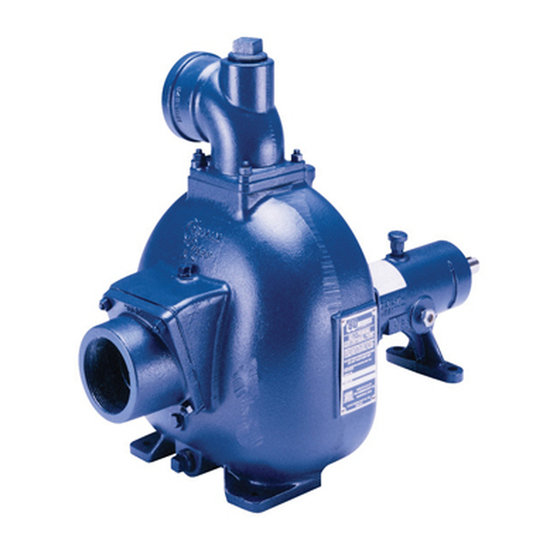
80 SERIES PUMP
MODEL
83B3−B
THE GORMAN-RUPP COMPANY D MANSFIELD, OHIO
www.grpumps.com
D
GORMAN-RUPP OF CANADA LIMITED
ST. THOMAS, ONTARIO, CANADA
Printed in U.S.A.
e
Copyright by the Gorman-Rupp Company
Advertisement
Table of Contents

Related Manuals for GORMAN-RUPP 83B3-B


Summary of Contents for GORMAN-RUPP 83B3-B
- Page 1 December 15, 1994 Rev. A 09-27-07 INSTALLATION, OPERATION, AND MAINTENANCE MANUAL WITH PARTS LIST 80 SERIES PUMP MODEL 83B3−B THE GORMAN-RUPP COMPANY D MANSFIELD, OHIO www.grpumps.com GORMAN-RUPP OF CANADA LIMITED ST. THOMAS, ONTARIO, CANADA Printed in U.S.A. Copyright by the Gorman-Rupp Company...
- Page 2 Valid serial number and e-mail address required. RECORD YOUR PUMP MODEL AND SERIAL NUMBER Please record your pump model and serial number in the spaces provided below. Your Gorman-Rupp distributor needs this information when you require parts or service. Pump Model:...
-
Page 3: Table Of Contents
TABLE OF CONTENTS INTRODUCTION ..........PAGE I −... - Page 4 TABLE OF CONTENTS (continued) PARTS LIST: Pump Model ............PAGE E −...
-
Page 5: Introduction
80 SERIES OM−00877 INTRODUCTION Thank You for purchasing a Gorman-Rupp pump. The following are used to alert maintenance per- Read this manual carefully to learn how to safely sonnel to procedures which require special atten- install and operate your pump. Failure to do so... -
Page 6: Safety - Section A
OM−00877 SAFETY - SECTION A This information applies to 80 Series ba- 6. Vent the pump slowly and cau- sic pumps. Gorman-Rupp has no con- tiously. trol over or particular knowledge of the 7. Drain the pump. power source which will be used. Refer... - Page 7 OM−00877 80 SERIES unit and the National Electric Code or closed discharge valve for long periods the applicable local code, the National of time. If operated against a closed dis- or local code shall take precedence. charge valve, pump components will deteriorate, and the liquid could come to a boil, build pressure, and cause the pump casing to rupture or explode.
-
Page 8: Installation − Section Bpage B
E, Page 1). Most of the information pertains to a standard For further assistance, contact your Gorman-Rupp static lift application where the pump is positioned distributor or the Gorman-Rupp Company. above the free level of liquid to be pumped. -
Page 9: Positioning Pump
E−1 to be sure your overall application allows Gorman-Rupp distributor or the factory to deter- pump to operate within the safe operation range. mine the repair or updating policy. Do not put the... -
Page 10: Gauges
80 SERIES OM−00877 cause excessive vibration, decreased bearing life, This pump is designed to handle up to 13/16 inch and increased shaft and seal wear. If hose-type (20,6 mm) diameter spherical solids. lines are used, they should have adequate support to secure them when filled with liquid and under Sealing pressure. -
Page 11: Discharge Lines
OM−00877 80 SERIES reduce the inlet velocity. Calculate the required on the increased opening size (area or diameter). submergence using the following formula based Figure 2. Recommended Minimum Suction Line Submergence vs. Velocity DISCHARGE LINES Siphoning If the application involves a high discharge head, gradually close the discharge Do not terminate the discharge line at a level lower throttling valve before stopping the pump. -
Page 12: Alignment
Check Rotation, Section C, before final alignment Figure 3A. Aligning Spider Type Couplings of the pump. When mounted at the Gorman-Rupp factory, driver and pump are aligned before shipment. Misalign- ment will occur in transit and handling. Pumps must be checked and realigned before operation. -
Page 13: V-Belt Drives
OM−00877 80 SERIES side. When the straightedge rests evenly on both V-BELT TENSIONING halves of the coupling, the coupling is in horizontal General Rules of Tensioning parallel alignment. If the coupling is misaligned, use a feeler gauge between the coupling and the For new v-belts, check the tension after 5, 20 and straightedge to measure the amount of misalign- 50 hours of operation and re-tension as required... - Page 14 Table 1 or 2 and ad- To use the Gorman-Rupp tensioner, measure the just the tension accordingly. Note that the tension belt span as shown in Figure 4. Position the bottom...
- Page 15 OM−00877 80 SERIES Table 1. Sheave Diameter (Inches) Table 2. Sheave Diameter (Millimeters) Deflection Force (Lbs.) Deflection Force (KG.) Belt Deflection Force Belt Deflection Force Uncogged Cogged Uncogged Cogged Hy-T Belts & Torque-Flex Hy-T Belts & Torque-Flex Uncogged & Machined Uncogged &...
-
Page 16: Operation − Section C
Only the Gorman-Rupp Company or an authorized Gorman-Rupp distributor may modify a pump or approve its use for handling volatile, flammable liquids. If the pump is used for handling volatile,... -
Page 17: Starting
OM−00877 80 SERIES STARTING OPERATION Lines With a Bypass Consult the operations manual furnished with the power source. Close the discharge throttling valve (if so equipped) so that the pump will not have to prime If the pump has been approved for use with petro- against the weight of the liquid in the discharge line. -
Page 18: Strainer Check
OM−00877 80 SERIES boil, build pressure, and cause the pump to rup- lift, and should then stabilize. If the vacuum reading ture or explode. If overheating occurs, stop the falls off rapidly after stabilization, an air leak exists. pump and allow it to completely cool before servic- Before checking for the source of the leak, check the point of installation of the vacuum gauge. - Page 19 OM−00877 80 SERIES curately by placing a contact-type thermometer rect level (see LUBRICATION in Section E). Bear- against the housing. Record this temperature for ing overheating can also be caused by shaft future reference. misalignment and/or excessive vibration. A sudden increase in bearing temperatures is a When pumps are first started, the bearings may warning that the bearings are at the point of failing seem to run at temperatures above normal.
-
Page 20: Troubleshooting − Section D
80 SERIES OM−00877 TROUBLESHOOTING − SECTION D Review all SAFETY information in Section A. Before attempting to open or service the pump: 1. Familiarize yourself with this man- ual. 2. Lock out or disconnect the power source to ensure that the pump will remain inoperative. - Page 21 OM−00877 80 SERIES TROUBLE POSSIBLE CAUSE PROBABLE REMEDY Impeller or other wearing parts worn Replace worn or damaged parts. PUMP STOPS OR FAILS TO DELIVER or damaged. Check that impeller is properly RATED FLOW OR centered and rotates freely. PRESSURE (cont.) Impeller clogged.
-
Page 22: Preventive Maintenance Schedule
Gorman-Rupp pump. For specific questions con- For new applications, a first inspection of wearing cerning your application, contact your Gorman- parts at 250 hours will give insight into the wear rate Rupp distributor or the Gorman-Rupp Company. -
Page 23: Pump Maintenance And Repair - Section E
OPERATING PERFORMANCE. STANDARD PERFORMANCE FOR PUMP MODEL 83B3−B Based on 70_ F (21_ C) clear water at sea level Contact the Gorman-Rupp Company to verify per- formance or part numbers. with minimum suction lift. Since pump installations are seldom identical, your performance may be dif- ference due to such factors as viscosity, specific gravity, elevation, temperature, and impeller trim. - Page 24 OM−00877 80 SERIES PARTS PAGE SECTION DRAWING Figure 1. Pump Model 83B3−B PAGE E − 2 MAINTENANCE & REPAIR...
-
Page 25: Parts List
PARTS LIST Pump Model 83B3−B (From S/N 1059514 up) If your pump serial number is followed by an N", your pump is NOT a standard production model. Contact the Gorman-Rupp Company to verify part numbers. ITEM PART NAME PART MAT’L... - Page 26 OM−0877 80 SERIES PUMP AND SEAL DISASSEMBLY 3. Allow the pump to completely cool AND REASSEMBLY if overheated. 4. Check the temperature before opening any covers, plates, or Review all SAFETY information in Section A. plugs. Follow the instructions on all tags, label and de- 5.
- Page 27 80 SERIES OM−00877 Pump Casing and Wear Plate Removal ler may also be loosened by using a long piece of heavy bar stock to pry against the arm of the lathe To service the impeller (2), wear plate assembly dog in a counterclockwise direction (when facing (36) or seal assembly (3), disconnect the dis- the drive end of the shaft) as shown in Figure 2.
- Page 28 OM−0877 80 SERIES If no further disassembly is required, see Seal Reassembly and Installation. Shaft And Bearing Removal And Disassembly To prevent damage during removal from the shaft, it is recommended that bearings When the pump is properly operated and main- be cleaned and inspected in place.
- Page 29 80 SERIES OM−00877 Replace the bearings, shaft, or pedestal if the out of position in shrinking. If movement has oc- proper bearing fit is not achieved. curred, use a suitably sized sleeve and a press to reposition the bearings. If bearing replacement is required, use a bearing If heating the bearings is not practical, use a suit- puller to remove the inboard and outboard bear- ably sized sleeve and an arbor (or hydraulic) press...
- Page 30 OM−0877 80 SERIES Seal Reassembly and Installation Handle the seal parts with extreme care to prevent damage. Be careful not to contaminate precision (Figures 1 and 2) finished faces; even fingerprints on the faces can shorten seal life. If necessary, clean the faces with a non-oil based solvent and a clean, lint-free tissue.
- Page 31 80 SERIES OM−00877 A clearance of .015 to .020 inch (0,38 to 0,51 mm) between the impeller and the seal plate is neces- sary for maximum pump efficiency. Measure this clearance and add or remove impeller shims until This seal is not designed for operation at this clearance is reached.
- Page 32 OM−0877 80 SERIES Suction Check Valve Installation Bearings If the check valve assembly (45) was disas- sembled, use the hardware (49 and 50) to secure The pedestal was fully lubricated when shipped the weights (47 and 48) to the new gasket (46). from the factory.
- Page 33 For U.S. and International Warranty Information, Please Visit www.grpumps.com/warranty or call: U.S.: 419−755−1280 International: +1−419−755−1352 For Canadian Warranty Information, Please Visit www.grcanada.com/warranty or call: 519−631−2870 THE GORMAN-RUPP COMPANY D MANSFIELD, OHIO GORMAN-RUPP OF CANADA LIMITED ST. THOMAS, ONTARIO, CANADA...
Need help?
Do you have a question about the 83B3-B and is the answer not in the manual?
Questions and answers