Table of Contents

Related Manuals for GORMAN-RUPP V3A60-B


Summary of Contents for GORMAN-RUPP V3A60-B
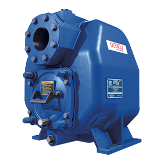
- Page 1 OM‐05815‐01 October 13, 2005 Rev. E 08‐21‐14 INSTALLATION, OPERATION, AND MAINTENANCE MANUAL WITH PARTS LIST ULTRA V PUMP MODEL V3A60‐B INCLUDING: /WW GORMAN‐RUPP PUMPS www.grpumps.com 2014 Gorman‐Rupp Pumps Printed in U.S.A.
- Page 2 Register your new Gorman‐Rupp pump online at www.grpumps.com Valid serial number and e‐mail address required. RECORD YOUR PUMP MODEL AND SERIAL NUMBER Please record your pump model and serial number in the spaces provided below. Your Gorman‐Rupp distributor needs this information when you require parts or service. Pump Model: Serial Number:...
-
Page 3: Table Of Contents
TABLE OF CONTENTS INTRODUCTION ..........PAGE I - 1 SAFETY - SECTION A . - Page 4 TABLE OF CONTENTS (continued) TROUBLESHOOTING - SECTION D ......PAGE D - 1 PREVENTIVE MAINTENANCE .
-
Page 5: Introduction
ULTRA V SERIES OM-05815 INTRODUCTION Thank You for purchasing a Gorman‐Rupp pump. HAZARD AND INSTRUCTION Read this manual carefully to learn how to safely DEFINITIONS install and operate your pump. Failure to do so could result in personal injury or damage to the The following are used to alert maintenance per... -
Page 6: Safety - Section A
ULTRA V SERIES OM-05815 SAFETY - SECTION A This information applies to Ultra V Se which may damage the pump or endan ries pumps. Gorman‐Rupp has no con ger personnel as a result of pump fail trol over or particular knowledge of the ure. - Page 7 OM-05815 ULTRA V SERIES Death or serious personal injury and Do not attempt to disengage any part of damage to the pump or components an overheated pump unit. Vapor pres can occur if proper lifting procedures sure within the pump casing can eject are not observed.
-
Page 8: Installation - Section B
ULTRA V SERIES OM-05815 INSTALLATION - SECTION B Review all SAFETY information in Section A. Check that the pump shaft rotates counter clockwise when facing the impeller. Since pump installations are seldom identical, this section offers only general recommendations and practices required to inspect, position, and ar... -
Page 9: Mounting
OM-05815 ULTRA V SERIES ing piping couplings in suction lines is not recom moved from the pump before lifting. Lift mended. the pump or component only as high as necessary and keep personnel away from suspended objects. Line Configuration Pump unit weights will vary depending on the Keep suction and discharge lines as straight as mounting and drive provided. -
Page 10: Strainers
ULTRA V SERIES OM-05815 stalled with the flat part of the reducers uppermost sump at a distance equal to 1 1/2 times the diame to avoid creating air pockets. Valves are not nor ter of the suction line. mally used in suction lines, but if a valve is used, install it with the stem horizontal to avoid air pock... -
Page 11: Discharge Lines
OM-05815 ULTRA V SERIES Figure 1. Recommended Minimum Suction Line Submergence vs. Velocity DISCHARGE LINES With high discharge heads, it is recommended that a throttling valve and a system check valve be in stalled in the discharge line to protect the pump from excessive shock pressure and reverse rota... -
Page 12: Automatic Air Release Valve
ULTRA V SERIES OM-05815 In low discharge head applications (less than 30 feet or 9 meters), it is recommended that the by pass line be run back to the wet well, and located 6 inches below the water level or cut‐off point of the If a manual shut‐off valve is installed in low level pump. -
Page 13: Air Release Valve Installation
OM-05815 ULTRA V SERIES Air Release Valve Installation tween the pump discharge port and the inlet side of the discharge check valve (see Figure 2). The inlet opening in the Air Release Valve is equipped with The Automatic Air Release Valve must be inde pendently mounted in a horizontal position be... -
Page 14: Coupled Drives
ULTRA V SERIES OM-05815 When mounted at the Gorman‐Rupp factory, driver and pump are aligned before shipment. Misalign ment will occur in transit and handling. Pumps must be checked and realigned before operation. Before checking alignment, tighten the foundation bolts. The pump casing feet and/or pedestal feet, and the driver mounting bolts should also be tightly secured. -
Page 15: Drive Belt Tensioning
OM-05815 ULTRA V SERIES Tighten the belts in accordance with the belt manu DRIVE BELT TENSIONING facturer's instructions. If the belts are too loose, they will slip; if the belts are too tight, there will be General Rules of Tensioning excessive power loss and possible bearing failure. -
Page 16: Operation - Section C
OM-05815 ULTRA V SERIES OPERATION - SECTION C Review all SAFETY information in Section A. Add liquid to the pump casing when: 1. The pump is being put into service for the Follow the instructions on all tags, labels and de first time. -
Page 17: Operation
OM-05815 ULTRA V SERIES If rotation is incorrect on a three‐phase motor, have pump components will deteriorate, and a qualified electrician interchange any two of the the liquid could come to a boil, build three phase wires to change direction. If rotation is pressure, and cause the pump casing to incorrect on a single‐phase motor, consult the liter... -
Page 18: Strainer Check
OM-05815 ULTRA V SERIES heated pump cautiously. It is recommended that shock waves can be transmitted to the pump and the pressure relief valve assembly be replaced at piping system. Close all connecting valves slowly. each overhaul, or any time the pump casing over heats and activates the valve. - Page 19 OM-05815 ULTRA V SERIES Checking bearing temperatures by hand is inaccu rect level (see LUBRICATION in MAINTENANCE rate. Bearing temperatures can be measured ac AND REPAIR). Bearing overheating can also be curately by placing a contact‐type thermometer caused by shaft misalignment and/or excessive vi against the housing.
- Page 20 ULTRA V SERIES OM-05815 TROUBLESHOOTING - SECTION D Review all SAFETY information in Section A. Before attempting to open or service the pump: 1. Familiarize yourself with this manual. 2. Lock out or disconnect the power source to ensure that the pump will remain inoperative.
- Page 21 OM-05815 ULTRA V SERIES TROUBLE POSSIBLE CAUSE PROBABLE REMEDY PUMP STOPS OR Strainer clogged. Check strainer and clean if neces FAILS TO DELIVER sary. RATED FLOW OR PRESSURE Suction intake not submerged at Check installation and correct sub proper level or sump too small. mergence as needed.
-
Page 22: Preventive Maintenance Schedule
ULTRA V SERIES OM-05815 in suction and discharge gauge readings (if so PREVENTIVE MAINTENANCE equipped) between regularly scheduled inspec tions can indicate problems that can be corrected Routine preventive maintenance of the pump will before system damage or catastrophic failure oc maintain peak operating performance. - Page 23 OM-05815 ULTRA V SERIES PUMP MAINTENANCE AND REPAIR - SECTION E MAINTENANCE AND REPAIR OF THE WEARING PARTS OF THE PUMP WILL MAINTAIN PEAK OPERATING PERFORMANCE. STANDARD PERFORMANCE FOR PUMP MODEL V3A60‐B, Including /WW Based on 70 F (21 C) clear water at sea level with Contact the Gorman‐Rupp Company to verify per...
- Page 24 OM-05815 ULTRA V SERIES PARTS PAGE ILLUSTRATION Figure 1. Pump Model V3A60-B (Including /WW) PAGE E - 2 MAINTENANCE & REPAIR...
-
Page 25: Parts List
OM-05815 ULTRA V SERIES PARTS LIST Pump Model V3A60-B (Including /WW) (From S/N 1321968 Up) If your pump serial number is followed by an “N”, your pump is NOT a standard production model. Contact the Gorman‐Rupp Company to verify part numbers. - Page 26 OM-05815 ULTRA V SERIES ILLUSTRATION Figure 2. Repair Rotating Assemblies PAGE E - 4 MAINTENANCE & REPAIR...
- Page 27 OM-05815 ULTRA V SERIES PARTS LIST Repair Rotating Assemblies Note: Order the complete Repair Rotating Assembly from the Pump Model Assembly Parts List on page E-3. Rotating Assemblies for /WW models also include all standard parts listed below. ITEM PART NAME PART ITEM PART NAME...
- Page 28 OM-05815 ULTRA V SERIES PUMP AND SEAL DISASSEMBLY AND REASSEMBLY Before attempting to open or service the Review all SAFETY information in Section A. pump: 1. Familiarize yourself with this man ual. Follow the instructions on all tags, label and decals 2.
- Page 29 ULTRA V SERIES OM-05815 Back Cover And Wear Plate Removal If removed, install the shaft key (22). Install a lathe dog on the drive end of the shaft (23) with the “V” (Figure 1) notch positioned over the shaft key. The wear plate (7) is easily accessible and may be With the impeller rotation still blocked, see Figure 3 serviced by removing the back cover assembly...
- Page 30 OM-05815 ULTRA V SERIES 9) and separate the seal plate (4) and gasket (5) from the bearing housing (7). Position the seal plate on a flat surface with the impeller side down. Use a wooden dowel or other suitable tool to press on the back side of the stationary seat until the APPROX.
- Page 31 ULTRA V SERIES OM-05815 Shaft and Bearing Reassembly and Installation strongly recommended that the bearings be replaced any time the shaft and bear (Figure 2) ings are removed. Clean the bearing housing, shaft and all compo nent parts (except the bearings) with a soft cloth Clean the bearing housing, shaft and all compo...
- Page 32 OM-05815 ULTRA V SERIES The bearings may be heated to ease installation. With the lip seal sleeve in place, lubricate the lip An induction heater, hot oil bath, electric oven, or seal area of the shaft, and slide the shaft and as hot plate may be used to heat the bearings.
- Page 33 ULTRA V SERIES OM-05815 gency, carefully wash all metallic parts in fresh cleaning solvent and allow to dry thoroughly. Inspect the seal components for wear, scoring, grooves, and other damage that might cause leak A new seal assembly should be installed age.
- Page 34 OM-05815 ULTRA V SERIES and secure it to the bearing housing with the hard STATIONARY SEAT ware (7 and 8). FULLY SEATED IN SEAL PLATE BORE To prevent damaging the shaft sleeve O‐ring (25) on the shaft threads, stretch the O‐ring over a piece of plastic tubing that the I.D.
- Page 35 ULTRA V SERIES OM-05815 Carefully wash all metallic parts in fresh cleaning the threads can cause the impeller to seize solvent and allow to dry thoroughly. to the shaft, making future removal difficult or impossible without damage to the im peller or shaft.
- Page 36 OM-05815 ULTRA V SERIES Back Cover Installation and Adjustment nuts (17) on diagonally opposing studs to press the back cover into the pump casing until the wear (Figures 1 and 8) plate just touches the impeller when the shaft is turned by hand.
- Page 37 ULTRA V SERIES OM-05815 Suction Check Valve Installation guards in place over the rotating parts. Exposed rotating parts can catch cloth (Figure 1) ing, fingers, or tools, causing severe in jury to personnel. Inspect the check valve assembly (26) and replace it if badly worn.
- Page 38 OM-05815 ULTRA V SERIES quently if the pump is operated continuously or in portant in areas where variable hot and stalled in an environment with rapid temperature cold temperatures are common. change. For cold weather operation, consult the factory or a lubricant supplier for the recommended grade of oil.
- Page 39 For U.S. and International Warranty Information, Please Visit www.grpumps.com/warranty or call: U.S.: 419-755-1280 International: +1-419-755-1352 For Canadian Warranty Information, Please Visit www.grcanada.com/warranty or call: 519-631-2870 GORMAN‐RUPP PUMPS...
Need help?
Do you have a question about the V3A60-B and is the answer not in the manual?
Questions and answers