Table of Contents
Advertisement
Quick Links
ABCDE
OM-06007-01
April 10, 2007
INSTALLATION, OPERATION,
AND MAINTENANCE MANUAL
WITH PARTS LIST
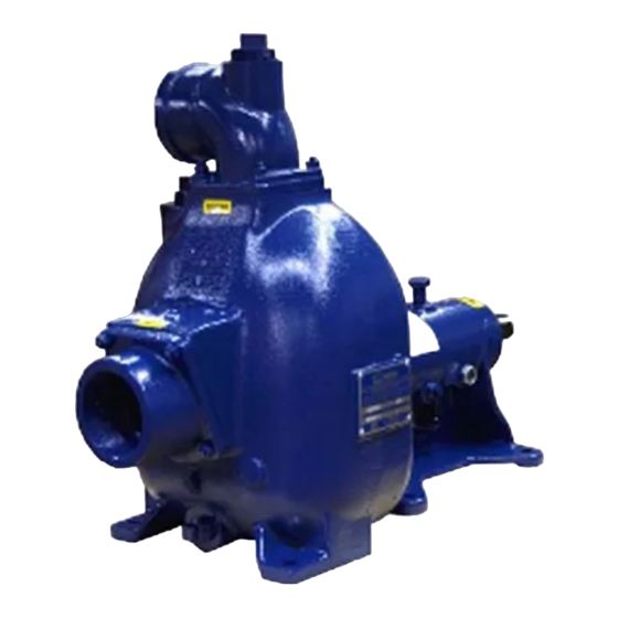
80 SERIES PUMP
MODEL
83B31−B
THE GORMAN-RUPP COMPANY D MANSFIELD, OHIO
www.grpumps.com
D
GORMAN-RUPP OF CANADA LIMITED
ST. THOMAS, ONTARIO, CANADA
Printed in U.S.A.
e
Copyright by the Gorman-Rupp Company
Advertisement
Table of Contents

Related Manuals for GORMAN-RUPP 83B31-B


Summary of Contents for GORMAN-RUPP 83B31-B
- Page 1 OM-06007-01 April 10, 2007 INSTALLATION, OPERATION, AND MAINTENANCE MANUAL WITH PARTS LIST 80 SERIES PUMP MODEL 83B31−B THE GORMAN-RUPP COMPANY D MANSFIELD, OHIO www.grpumps.com GORMAN-RUPP OF CANADA LIMITED ST. THOMAS, ONTARIO, CANADA Printed in U.S.A. Copyright by the Gorman-Rupp Company...
- Page 2 Valid serial number and e-mail address required. RECORD YOUR PUMP MODEL AND SERIAL NUMBER Please record your pump model and serial number in the spaces provided below. Your Gorman-Rupp distributor needs this information when you require parts or service. Pump Model:...
-
Page 3: Table Of Contents
TABLE OF CONTENTS INTRODUCTION ..........PAGE I −... - Page 4 TABLE OF CONTENTS (continued) TROUBLESHOOTING − SECTION D ......PAGE D − 1 PREVENTIVE MAINTENANCE .
-
Page 5: Introduction
80 SERIES OM−06007 INTRODUCTION Thank You for purchasing a Gorman-Rupp pump. The following are used to alert maintenance per- Read this manual carefully to learn how to safely sonnel to procedures which require special atten- install and operate your pump. Failure to do so... -
Page 6: Safety - Section A
OM−06007 SAFETY - SECTION A This information applies to 80 Series ba- 6. Vent the pump slowly and cau- sic pumps. Gorman-Rupp has no con- tiously. trol over or particular knowledge of the 7. Drain the pump. power source which will be used. Refer... - Page 7 OM−06007 80 SERIES unit and the National Electric Code or closed discharge valve for long periods the applicable local code, the National of time. If operated against a closed dis- or local code shall take precedence. charge valve, pump components will deteriorate, and the liquid could come to a boil, build pressure, and cause the pump casing to rupture or explode.
-
Page 8: Installation − Section Bpage B
E, Page 1). Most of the information pertains to a standard For further assistance, contact your Gorman-Rupp static lift application where the pump is positioned distributor or the Gorman-Rupp Company. above the free level of liquid to be pumped. -
Page 9: Preinstallation Inspection
If the maximum shelf life has been exceeded, or if anything appears to be abnormal, contact your Pump performance is adversely effected by in- Gorman-Rupp distributor or the factory to deter- creased suction lift, discharge elevation, and fric- mine the repair or updating policy. Do not put the tion losses. -
Page 10: Materials
80 SERIES OM−06007 Materials line must always slope upward to the pump from the source of the liquid being pumped; if the line Either pipe or hose maybe used for suction and slopes down to the pump at any point along the discharge lines;... -
Page 11: Suction Line Positioning
OM−06007 80 SERIES If there is a liquid flow from an open pipe into the tance equal to at least 3 times the diameter of the sump, the flow should be kept away from the suc- suction pipe. tion inlet because the inflow will carry air down into Suction Line Positioning the sump, and air entering the suction line will re- duce pump efficiency. -
Page 12: Bypass Lines
NOTE Check Rotation, Section C, before final alignment of the pump. When mounted at the Gorman-Rupp factory, driver and pump are aligned before shipment. Misalign- ment will occur in transit and handling. Pumps must be checked and realigned before operation. -
Page 13: Drive Belts
OM−06007 80 SERIES MISALIGNED: MISALIGNED: ALIGNED: SHAFTS SHAFTS SHAFTS PARALLEL AND NOT PARALLEL NOT IN LINE SHEAVES IN LINE Figure 3C. Alignment of V-Belt Driven Pumps Figure 3B. Aligning Non-Spider Type Tighten the belts in accordance with the belt manu- Couplings facturer’s instructions. -
Page 14: Grounding
80 SERIES OM−06007 a tight electrical connection with the rod and the GROUNDING pump. If the pump has been approved to pump volatile or flammable liquids, the unit must be grounded by attaching the ground wire assembly to a ground rod in order to eliminate electrostatic build-up by Inspect and test the ground wire assembly the liquid being pumped. -
Page 15: Operation − Section C
Only the Gorman-Rupp Company or an authorized Gorman-Rupp distributor may modify a pump or approve its use for handling volatile, flammable liquids. If the pump is used for handling volatile,... -
Page 16: Starting
OM−06007 80 SERIES STARTING OPERATION Lines With a Bypass Consult the operations manual furnished with the power source. Close the discharge throttling valve (if so equipped) so that the pump will not have to prime If the pump has been approved for use with petro- against the weight of the liquid in the discharge line. -
Page 17: Strainer Check
OM−06007 80 SERIES boil, build pressure, and cause the pump to rup- lift, and should then stabilize. If the vacuum reading ture or explode. If overheating occurs, stop the falls off rapidly after stabilization, an air leak exists. pump and allow it to completely cool before servic- Before checking for the source of the leak, check the point of installation of the vacuum gauge. - Page 18 OM−06007 80 SERIES curately by placing a contact-type thermometer rect level (see LUBRICATION in Section E). Bear- against the housing. Record this temperature for ing overheating can also be caused by shaft future reference. misalignment and/or excessive vibration. A sudden increase in bearing temperatures is a When pumps are first started, the bearings may warning that the bearings are at the point of failing seem to run at temperatures above normal.
- Page 19 80 SERIES OM−06007 TROUBLESHOOTING − SECTION D Review all SAFETY information in Section A. Before attempting to open or service the pump: 1. Familiarize yourself with this man- ual. 2. Lock out or disconnect the power source to ensure that the pump will remain inoperative.
- Page 20 OM−06007 80 SERIES TROUBLE POSSIBLE CAUSE PROBABLE REMEDY Impeller or other wearing parts worn Replace worn or damaged parts. PUMP STOPS OR FAILS TO DELIVER or damaged. Check that impeller is properly RATED FLOW OR centered and rotates freely. PRESSURE (cont.) Impeller clogged.
- Page 21 Gorman-Rupp pump. For specific questions con- For new applications, a first inspection of wearing cerning your application, contact your Gorman- parts at 250 hours will give insight into the wear rate Rupp distributor or the Gorman-Rupp Company.
- Page 22 OPERATING PERFORMANCE. STANDARD PERFORMANCE FOR PUMP MODEL 83B52−B Based on 70_ F (21_ C) clear water at sea level Contact the Gorman-Rupp Company to verify per- formance or part numbers. with minimum suction lift. Since pump installations are seldom identical, your performance may be dif- ference due to such factors as viscosity, specific gravity, elevation, temperature, and impeller trim.
- Page 23 OM−06007 80 SERIES SECTION DRAWING PARTS PAGE Figure 1. Pump Model 83B31−B PAGE E − 2 MAINTENANCE & REPAIR...
- Page 24 PARTS LIST Pump Model 83B31−B (From S/N 1364724 up) If your pump serial number is followed by an N", your pump is NOT a standard production model. Contact the Gorman-Rupp Company to verify part numbers. ITEM PART NAME PART MAT’L...
- Page 25 OM−06007 80 SERIES PUMP AND SEAL DISASSEMBLY 5. Close the suction and discharge valves. AND REASSEMBLY 6. Vent the pump slowly and cau- Review all SAFETY information in Section A. tiously. 7. Drain the pump. Follow the instructions on all tags, label and de- cals attached to the pump.
- Page 26 80 SERIES OM−06007 charge piping. Remove the hardware securing the the lathe dog and wood block and unscrew the im- pump casing (1) to the base. peller from the shaft. Remove the nuts (33) securing the pump casing Turn and gasket set (35) to the pedestal (18) and seal Counterclockwise plate (34).
- Page 27 OM−06007 80 SERIES Shaft And Bearing Removal And Disassembly When the pump is properly operated and main- tained, the pedestal should not require disassem- To prevent damage during removal from bly. Disassemble the shaft and bearings only the shaft, it is recommended that bearings when there is evidence of wear or damage.
- Page 28 80 SERIES OM−06007 Replace the bearings, shaft, or pedestal if the curred, use a suitably sized sleeve and a press to proper bearing fit is not achieved. reposition the bearings. If heating the bearings is not practical, use a suit- If bearing replacement is required, use a bearing ably sized sleeve and an arbor (or hydraulic) press puller to remove the inboard and outboard bear-...
- Page 29 OM−06007 80 SERIES Seal Reassembly and Installation finished faces; even fingerprints on the faces can shorten seal life. If necessary, clean the faces with a (Figures 1 and 3) non-oil based solvent and a clean, lint-free tissue. Wipe lightly in a concentric pattern to avoid Clean the seal cavity and shaft with a cloth soaked scratching the faces.
- Page 30 80 SERIES OM−06007 After the back clearance is set, secure the impeller with the hardware (37, 38 and 39). Pump Casing Installation This seal is not designed for operation at If the wear plate assembly (36) was removed, posi- temperatures above 160_F (71_C). Do not tion the replacement wear plate assembly squarely use at higher operating temperatures.
- Page 31 OM−06007 80 SERIES side of the pump casing. Install the suction flange Bearings (52) and secure with the nuts (54). Check the oper- The pedestal was fully lubricated when shipped ation of the check valve to ensure proper seating from the factory. Check the oil level regularly and free movement.
- Page 32 For U.S. and International Warranty Information, Please Visit www.grpumps.com/warranty or call: U.S.: 419−755−1280 International: +1−419−755−1352 For Canadian Warranty Information, Please Visit www.grcanada.com/warranty or call: 519−631−2870 THE GORMAN-RUPP COMPANY D MANSFIELD, OHIO GORMAN-RUPP OF CANADA LIMITED ST. THOMAS, ONTARIO, CANADA...
Need help?
Do you have a question about the 83B31-B and is the answer not in the manual?
Questions and answers