Table of Contents
Advertisement
Quick Links
ACE
OM-00856-02
April 4, 1980
Rev. C 09-19-07
INSTALLATION, OPERATION,
AND MAINTENANCE MANUAL
WITH PARTS LIST
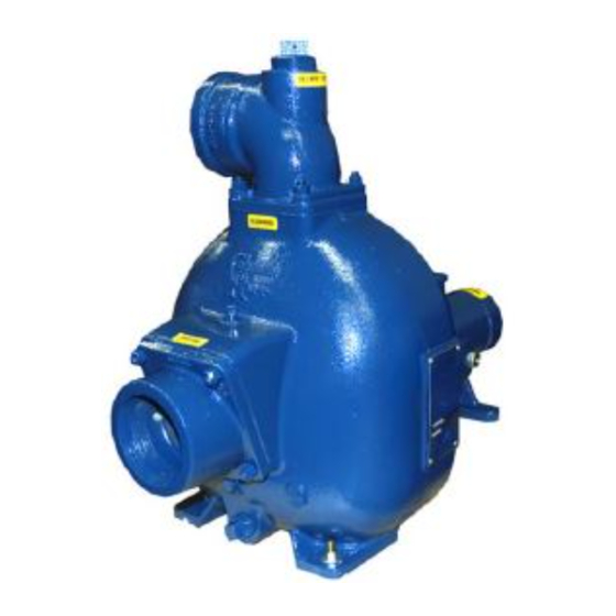
80 SERIES PUMP
MODEL
83A2-B
THE GORMAN-RUPP COMPANY D MANSFIELD, OHIO
www.grpumps.com
D
GORMAN-RUPP OF CANADA LIMITED
ST. THOMAS, ONTARIO, CANADA
Printed in U.S.A.
e
Copyright by the Gorman-Rupp Company
Advertisement
Table of Contents

Related Manuals for GORMAN-RUPP 83A2-B


Summary of Contents for GORMAN-RUPP 83A2-B
- Page 1 April 4, 1980 Rev. C 09-19-07 INSTALLATION, OPERATION, AND MAINTENANCE MANUAL WITH PARTS LIST 80 SERIES PUMP MODEL 83A2-B THE GORMAN-RUPP COMPANY D MANSFIELD, OHIO www.grpumps.com GORMAN-RUPP OF CANADA LIMITED ST. THOMAS, ONTARIO, CANADA Printed in U.S.A. Copyright by the Gorman-Rupp Company...
- Page 2 Valid serial number and e-mail address required. RECORD YOUR PUMP MODEL AND SERIAL NUMBER Please record your pump model and serial number in the spaces provided below. Your Gorman-Rupp distributor needs this information when you require parts or service. Pump Model:...
-
Page 3: Table Of Contents
TABLE OF CONTENTS INTRODUCTION ..........PAGE I −... - Page 4 TABLE OF CONTENTS (continued) PUMP MAINTENANCE AND REPAIR - SECTION E ....PAGE E − 1 STANDARD PERFORMANCE CURVE ........PAGE E −...
-
Page 5: Introduction
80 SERIES OM−00856 INTRODUCTION Thank You for purchasing a Gorman-Rupp pump. The following are used to alert maintenance per- Read this manual carefully to learn how to safely sonnel to procedures which require special atten- install and operate your pump. Failure to do so... -
Page 6: Safety - Section A
Gorman-Rupp has no con- Do not attempt to pump liquids for trol over or particular knowledge of the which the pump, driver and/or controls power source which will be used. Refer... - Page 7 OM−00856 80 SERIES Overheated pumps can cause severe Never run this pump backwards. Be cer- burns and injuries. If overheating of the tain that rotation is correct before fully pump occurs: engaging the pump. 1. Stop the pump immediately. 2. Ventilate the area. 3.
-
Page 8: Installation − Section Bpage B
10 p.s.i. range the pump and piping. For further assistance, contact your Gorman-Rupp Most of the information pertains to a standard distributor or the Gorman-Rupp Company. static lift application where the pump is positioned above the free level of liquid to be pumped. -
Page 9: Positioning Pump
See the performance curve on Page Gorman-Rupp distributor or the factory to deter- E−1 to be sure your overall application allows mine the repair or updating policy. Do not put the pump to operate within the safe operation range. -
Page 10: Gauges
80 SERIES OM−00856 Lines near the pump must be independently sup- line, and that the openings will not permit passage ported to avoid strain on the pump which could of solids larger than the solids handling capability cause excessive vibration, decreased bearing life, of the pump. -
Page 11: Discharge Lines
OM−00856 80 SERIES reduce the inlet velocity. Calculate the required NOTE submergence using the following formula based The pipe submergence required may be reduced on the increased opening size (area or diameter). by installing a standard pipe increaser fitting at the end of the suction line. -
Page 12: Alignment
Check Rotation, Section C, before final alignment Figure 3A. Aligning Spider Type Couplings of the pump. When mounted at the Gorman-Rupp factory, driver and pump are aligned before shipment. Misalign- ment will occur in transit and handling. Pumps must be checked and realigned before operation. -
Page 13: V-Belt Tensioning
Ideal v-belt tension is the lowest tension at which To use the Gorman-Rupp tensioner, measure the the belt will not slip under peak load conditions. Do belt span as shown in Figure 4. Position the bottom not over-tension v-belts. - Page 14 80 SERIES OM−00856 er at the measured belt span. Set the small O-ring Read the force applied from the bottom of the small on the deflection force scale to zero. O-ring on the deflection force scale. Compare this force with the value shown in Table 1 or 2 and ad- Place the tension tester squarely on the belt at the just the tension accordingly.
- Page 15 OM−00856 80 SERIES Table 1. Sheave Diameter (Inches) Table 2. Sheave Diameter (Millimeters) Deflection Force (Lbs.) Deflection Force (KG.) Belt Deflection Force Belt Deflection Force Uncogged Cogged Uncogged Cogged Hy-T Belts & Torque-Flex Hy-T Belts & Torque-Flex Uncogged & Machined Uncogged &...
-
Page 16: Operation − Section C
OM−00856 80 SERIES OPERATION − SECTION C Review all SAFETY information in Section A. Add liquid to the pump casing when: 1. The pump is being put into service for the Follow the instructions on all tags, labels and first time. decals attached to the pump. -
Page 17: Operation
OM−00856 80 SERIES sprinkler heads, and any other fixtures connected from the shaft and seriously damage the to the line. When the discharge line is completely pump. filled, adjust the throttling valve to the required flow Consult the operating manual furnished with the rate. -
Page 18: Pump Vacuum Check
OM−00856 80 SERIES equipment. If backflushing is absolutely neces- Cold Weather Preservation sary, liquid pressure must be limited to 50% of the In below freezing conditions, drain the pump to maximum permissible operating pressure shown prevent damage from freezing. Also, clean out any on the pump performance curve (see Section E, solids by flushing with a hose. -
Page 19: Troubleshooting − Section D
80 SERIES OM−00856 TROUBLESHOOTING − SECTION D Review all SAFETY information in Section A. Before attempting to open or service the pump: 1. Familiarize yourself with this man- ual. 2. Lock out or disconnect the power source to ensure that the pump will remain inoperative. - Page 20 OM−00856 80 SERIES TROUBLE POSSIBLE CAUSE PROBABLE REMEDY Impeller or other wearing parts worn Replace worn or damaged parts. PUMP STOPS OR FAILS TO DELIVER or damaged. Check that impeller is properly RATED FLOW OR centered and rotates freely. PRESSURE (cont.) Impeller clogged.
-
Page 21: Preventive Maintenance
Gorman-Rupp pump. For specific questions con- For new applications, a first inspection of wearing cerning your application, contact your Gorman- parts at 250 hours will give insight into the wear rate Rupp distributor or the Gorman-Rupp Company. - Page 22 OPERATING PERFORMANCE. STANDARD PERFORMANCE FOR PUMP MODEL 83A2−B Based on 70_ F (21_ C) clear water at sea level Contact the Gorman-Rupp Company to verify per- formance or part numbers. with minimum suction lift. Since pump installations are seldom identical, your performance may be dif- ference due to such factors as viscosity, specific gravity, elevation, temperature, and impeller trim.
- Page 23 80 SERIES OM−00856 SECTION DRAWING PARTS PAGE Figure 1. Pump Model 83A2−B MAINTENANCE & REPAIR PAGE E − 2...
- Page 24 PARTS LIST Pump Model 83A2-B (From S/N 732174 Up) If your pump serial number is followed by an N", your pump is NOT a standard production model. Contact the Gorman-Rupp Company to verify part numbers. ITEM PART NAME PART MAT’L...
- Page 25 80 SERIES OM−00856 PUMP AND SEAL DISASSEMBLY 4. Check the temperature before opening any covers, plates, or AND REASSEMBLY plugs. 5. Close the suction and discharge Review all SAFETY information in Section A. valves. 6. Vent the pump slowly and cau- Follow the instructions on all tags, label and de- tiously.
- Page 26 OM−00856 80 SERIES wise until it rests against the cover (see Figure 4) to Seal Removal and Disassembly prevent the grease in the cup from escaping. Re- Remove the outer rotating element. Slide the seal move the grease cup and piping (9, 10 and 11). plate, shaft sleeve, and remaining seal parts off the shaft as a unit.
- Page 27 80 SERIES OM−00856 Remove the setscrews (22) from the bearing re- Clean the bearings thoroughly in fresh cleaning tainer (19) and install two machine screws solvent. Dry the bearings with filtered compressed (#10−32 x 1−inch long, not supplied). Pry the re- air and coat with light oil.
- Page 28 OM−00856 80 SERIES oil and the container must be absolutely clean. If Position the oil seal (20) in the bearing retainer (19) the oil has been previously used, it must be thor- with the lip positioned as shown in Figure 1. Press oughly filtered.
- Page 29 80 SERIES OM−00856 non-oil based solvent and a clean, lint-free tissue. If a replacement seal is being used, remove it from Wipe lightly in a concentric pattern to avoid the container and inspect the precision finished scratching the faces. faces to ensure that they are free of any foreign matter.
- Page 30 OM−00856 80 SERIES Slide the inboard rotating element into the lubri- Pump Casing and Wear Plate Installation cated seal liner with the chamfered side toward the If the wear plate assembly (36) was removed, shaft sholder. install the new wear plate in the pump casing and Subassemble the inboard stationary seat, packing secure it with the hardware (37, 38, 40 and 41).
- Page 31 80 SERIES OM−00856 LUBRICATION capes from the relief hole. Turn the grease cup arm counterclockwise until it is at the top of the stem; this will release the spring to apply grease to the Seal Assembly seal (see Figure 4). Fill the grease cup (9) through the grease fitting with No.
- Page 32 For U.S. and International Warranty Information, Please Visit www.grpumps.com/warranty or call: U.S.: 419−755−1280 International: +1−419−755−1352 For Canadian Warranty Information, Please Visit www.grcanada.com/warranty or call: 519−631−2870 THE GORMAN-RUPP COMPANY D MANSFIELD, OHIO GORMAN-RUPP OF CANADA LIMITED ST. THOMAS, ONTARIO, CANADA...
Need help?
Do you have a question about the 83A2-B and is the answer not in the manual?
Questions and answers