Table of Contents
Advertisement
Quick Links
ABEGQ
OM-01155-04
December 5, 1991
Rev. F 1-05-07
INSTALLATION, OPERATION,
AND MAINTENANCE MANUAL
WITH PARTS LIST
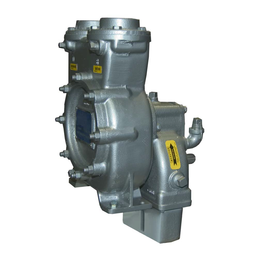
0 SERIES PUMP
MODEL
02F1−GR
THE GORMAN-RUPP COMPANY D MANSFIELD, OHIO
www.grpumps.com
D
GORMAN-RUPP OF CANADA LIMITED
ST. THOMAS, ONTARIO, CANADA
Printed in U.S.A.
e
Copyright by the Gorman-Rupp Company
Advertisement
Table of Contents

Related Manuals for GORMAN-RUPP 02F1?GR


Summary of Contents for GORMAN-RUPP 02F1?GR
- Page 1 December 5, 1991 Rev. F 1-05-07 INSTALLATION, OPERATION, AND MAINTENANCE MANUAL WITH PARTS LIST 0 SERIES PUMP MODEL 02F1−GR THE GORMAN-RUPP COMPANY D MANSFIELD, OHIO www.grpumps.com GORMAN-RUPP OF CANADA LIMITED ST. THOMAS, ONTARIO, CANADA Printed in U.S.A. Copyright by the Gorman-Rupp Company...
- Page 2 Valid serial number and e-mail address required. RECORD YOUR PUMP MODEL AND SERIAL NUMBER Please record your pump model and serial number in the spaces provided below. Your Gorman-Rupp distributor needs this information when you require parts or service. Pump Model:...
-
Page 3: Table Of Contents
TABLE OF CONTENTS INTRODUCTION ..........PAGE I −... - Page 4 TABLE OF CONTENTS (continued) PUMP MAINTENANCE AND REPAIR - SECTION E ....PAGE E − 1 PERFORMANCE CURVE ........... PAGE E −...
-
Page 5: Introduction
0 SERIES OM-01155 INTRODUCTION Thank You for purchasing a Gorman-Rupp pump. The following are used to alert maintenance per- Read this manual carefully to learn how to safely sonnel to procedures which require special atten- install and operate your pump. Failure to do so... -
Page 6: Safety - Section A
0 SERIES OM-01155 SAFETY − SECTION A These warnings apply to 0 Series power take-off pumps. Refer to the manual accompanying the power source before attempting to begin operation. If this pump is used with volatile and/or Because pump installations are seldom flammable liquids, be certain proper identical, this manual cannot possibly safety practices are followed before op-... - Page 7 OM−01155 0 SERIES to disconnect the drive shaft or remove the pump. Be sure the pump is properly reinstalled and secure before opera- tion. Do not operate the pump against a closed discharge valve for long periods of time. If operated against a closed dis- charge valve, pump components will deteriorate, and the liquid could come to a boil, build pressure, and cause the...
-
Page 8: Installation − Section Bpage B
Do not test or operate your pump and in- quate lubrication. Consult the factory for details. tegral gearbox before reading the in- stallation and operation instructions in For further assistance, contact your Gorman-Rupp this manual. distributor or the Gorman-Rupp Company. This pump is a self-priming centrifugal model with an integral gearbox assembly. -
Page 9: Preinstallation Inspection
Gorman-Rupp distributor or the factory to deter- Drain the pump and remove all customer-installed mine the repair or updating policy. Do not put the... -
Page 10: Alignment
0 SERIES OM−01155 The alignment of the pump and its power source is critical for trouble-free mechanical operation. Be- fore checking alignment, make sure that the gear- box mounting bolts are tight. The pump assembly can be seriously damaged if the cables or chains used to lift When connecting the universal joint drive shaft as- and move the unit are improperly wrapped sembly to a PTO unit, install, support, and align the... -
Page 11: Suction And Discharge Piping
OM−01155 0 SERIES LUGS MUST BE IN LINE, REGARDLESS OF OPERATING ANGLE SHOWN BELOW LUG ALIGNMENT SHAFTS PARALLEL, ANGLES EQUAL SHAFTS NOT PARALLEL, ANGLES EQUAL Figure 3. Proper Installation And Alignment of Universal Assembly SUCTION AND DISCHARGE PIPING tors, related piping and safety accessories. Some of the accessories are available from Gorman- Rupp as optional equipment. -
Page 12: Piping
0 SERIES OM−01155 SCHEMATIC SYSTEM USING EDUCTOR FOR DISPENSING AND FILLING Figure 3. Typical Installation Using Educator For Filling And Dispensing SCHEMATIC SYSTEM USING PUMP FOR DISPENSING AND FILLING Figure 4. Typical Installation Using Pump For Filling And Dispensing Piping A suction strainer was not furnished with this pump since it is not designed to handle liquids containing All piping material must be compatible with the liq-... -
Page 13: Sealing
Valves charge piping, carefully check the storage tank and piping for construction debris Gorman-Rupp manufactures several sizes of flow- such as nuts, bolts, wire, weld slag, and diverting (FDF) valves for use in truck-mounted pumping applications. The valves are designed to other foreign material. -
Page 14: Siphoning
Otherwise, a si- phoning action causing damage to the pump could result. Contact the Gorman-Rupp Company or an autho- Eductors rized distributor for specifications and perform- An eductor may be used in conjunction with an ance data on eductors or FDF valves. -
Page 15: Operation − Section C
OM−01155 0 SERIES OPERATION − SECTION C Review all SAFETY information in Section A. Add liquid to the pump casing when: 1. The pump is being put into service for the Follow the instructions on all tags, labels and first time. decals attached to the pump. -
Page 16: Drive
OM−01155 0 SERIES pump could be damaged and performance ad- Liquid Temperature And Overheating versely affected by incorrect rotation. If pump per- formance is not within the specified limits (see the The maximum liquid temperature for this pump is curve on Page E−1), check the direction of rotation 160_ F (71_C). -
Page 17: Pump Vacuum Check
OM−01155 0 SERIES Pump Vacuum Check Since this pump does not have a suction check valve, the discharge line must be fitted with a check If the application involves a high discharge valve if a pump vacuum reading is to be taken. head, gradually close the discharge throttling valve before stopping the pump. -
Page 18: Troubleshooting − Section D
0 SERIES OM−01155 TROUBLESHOOTING − SECTION D Review all SAFETY information in Section A. Before attempting to open or service the pump: 1. Familiarize yourself with this manual. 2. Switch off the vehicle ignition and re- move the key, or take other precau- tions to ensure that the pump will re- main inoperative. - Page 19 OM−01155 0 SERIES TROUBLE POSSIBLE CAUSE PROBABLE REMEDY Impeller or other wearing parts worn Replace worn or damaged parts. PUMP STOPS OR FAILS TO DELIVER or damaged. Check that impeller is properly cen- RATED FLOW OR tered and rotates freely. PRESSURE (cont.) Suction lift or discharge head too high.
-
Page 20: Preventive Maintenance
Gorman-Rupp pump. For specific questions con- For new applications, a first inspection of wearing cerning your application, contact your Gorman- parts at 250 hours will give insight into the wear rate Rupp distributor or the Gorman-Rupp Company. - Page 21 OPERATING PERFORMANCE. STANDARD PERFORMANCE FOR PUMP MODEL 02F1−GR Based on 70_ F (21_ C) clear water corrected to Contact the Gorman-Rupp Company to verify per- 0.8 specific gravity at sea level with minimum suc- formance or part numbers. tion lift. Since pump installations are seldom identi-...
- Page 22 OM−01155 0 SERIES SECTION DRAWING PARTS PAGE Figure 1. Pump Model 02F1−GR PAGE E − 2 MAINTENANCE & REPAIR...
- Page 23 PARTS LIST Pump Model 02F1−GR (From S/N 642659 up) If your pump serial number is followed by an N", your pump is NOT a standard production model. Contact the Gorman-Rupp Company to verify part numbers. ITEM PART MAT’L PART NAME...
- Page 24 OM−01155 0 SERIES Figure 2. 44161−020 Gear Box Assembly PAGE E − 4 MAINTENANCE & REPAIR...
- Page 25 0 SERIES OM−01155 PARTS LIST 44161−020 Gear Box Assembly ITEM PART MAT’L PART NAME NUMBER CODE PINION SHAFT 38521−016 16020 BALL BEARING 23275−206 −−− SPACER SLEEVE 8104 15160 PIPE PLUG 15079 GEAR BOX 8103B 10010 GASKET 8097G 18000 AIR VENT S1530 −−−...
- Page 26 OM−01155 0 SERIES PUMP AND SEAL DISASSEMBLY 5. Close the suction and discharge valves. 6. Vent the pump slowly and cau- Review all warnings in Section A. tiously. Follow the instructions on all tags, label and de- 7. Drain the pump. cals attached to the pump.
- Page 27 0 SERIES OM−01155 Impeller Removal while driving the shaft out. Once the assemblies have been separated, secure the shaft gear teeth in (Figure 1) a soft-jawed vice and proceed with the impeller re- moval. The impeller (2), wear ring (5) and seal assembly (3) may serviced by removing the cover plate (16).
- Page 28 OM−01155 0 SERIES Pump Disassembly (Figure 1) Most cleaning solvents are toxic and If the pump casing, oil seal (4) or gearbox assem- flammable. Use them only in a well-ven- bly (9) requires replacement, the casing must be tilated area free from excessive heat, separated from the gearbox housing (5, Figure 2).
- Page 29 0 SERIES OM−01155 Wipe lightly in a concentric pattern to avoid sparks, and flame. Read and follow all scratching the faces. precautions printed solvent containers. Inspect the seal components for wear, scoring, grooves, and other damage that might cause leak- The seal is not normally reused because wear pat- age.
- Page 30 OM−01155 0 SERIES ing face, and press the stationary seat into the NOTE pump casing until fully seated. A push tube cut Do not install the pipe plug in the gearbox until the from a length of plastic pipe would aid this installa- gearbox is properly lubricated as described in LU- tion.
- Page 31 0 SERIES OM−01155 Reposition the gearbox housing on the press with GEARBOX DISASSEMBLY the pump side down, and press the pinion shaft (1) (Figure 2) and bearings (2 and 12) from the housing. After removing the shafts and bearings, clean and When the pump is properly operated and main- inspect the bearings in place as follows.
- Page 32 OM−01155 0 SERIES housing. Replace the bearings, shaft, or gearbox housing if the proper bearing fit is not achieved. If the bearings require replacement, use a suitable Use caution when handling hot bear- puller to remove them from the shafts. ings to prevent burns.
- Page 33 0 SERIES OM−01155 Figure 5. Fixture Dimensions, Drive Gear And Shaft Installation Center the inboard spacer sleeve (3) on the inner bearing race. Center the drive gear (25) in the gear- box housing and engage the teeth of the pinion shaft.
- Page 34 OM−01155 0 SERIES level hole. Always clean the drain plug thoroughly (7), which are shipped loose. The air vent before reinstalling it. must be installed to prevent the gearbox from overheating during operation. SAE RATING TEMPERATURE RANGE The gearbox assembly was lubricated and Below 40 _F/4 _C tested before it was shipped from the facto- From 40 _F/4 _C to 100 _F/38 _C...
- Page 35 For U.S. and International Warranty Information, Please Visit www.grpumps.com/warranty or call: U.S.: 419−755−1280 International: +1−419−755−1352 For Canadian Warranty Information, Please Visit www.grcanada.com/warranty or call: 519−631−2870 THE GORMAN-RUPP COMPANY D MANSFIELD, OHIO GORMAN-RUPP OF CANADA LIMITED ST. THOMAS, ONTARIO, CANADA...
Need help?
Do you have a question about the 02F1?GR and is the answer not in the manual?
Questions and answers