Table of Contents
Advertisement
Quick Links
OM‐00862‐02
April 8, 1980
Rev. D 11‐09‐21
INSTALLATION, OPERATION,
AND MAINTENANCE MANUAL
WITH PARTS LIST
80 SERIES PUMP
MODEL
83A3-B
THE GORMAN‐RUPP COMPANY D MANSFIELD, OHIO
www.grpumps.com
D
GORMAN‐RUPP OF CANADA LIMITED
ST. THOMAS, ONTARIO, CANADA
Printed in U.S.A.
e
Copyright by the Gorman‐Rupp Company
Advertisement
Table of Contents

Subscribe to Our Youtube Channel
Related Manuals for GORMAN-RUPP 83A3-B


Summary of Contents for GORMAN-RUPP 83A3-B
- Page 1 April 8, 1980 Rev. D 11‐09‐21 INSTALLATION, OPERATION, AND MAINTENANCE MANUAL WITH PARTS LIST 80 SERIES PUMP MODEL 83A3-B THE GORMAN‐RUPP COMPANY D MANSFIELD, OHIO www.grpumps.com GORMAN‐RUPP OF CANADA LIMITED ST. THOMAS, ONTARIO, CANADA Printed in U.S.A. Copyright by the Gorman‐Rupp Company...
- Page 2 Register your new Gorman‐Rupp pump online at www.grpumps.com Valid serial number and e‐mail address required. RECORD YOUR PUMP MODEL AND SERIAL NUMBER Please record your pump model and serial number in the spaces provided below. Your Gorman‐Rupp distributor needs this information when you require parts or service. Pump Model: Serial Number:...
-
Page 3: Table Of Contents
TABLE OF CONTENTS INTRODUCTION ..........PAGE I - 1 SAFETY ‐... - Page 4 TABLE OF CONTENTS (continued) TROUBLESHOOTING - SECTION D ......PAGE D - 1 PREVENTIVE MAINTENANCE .
-
Page 5: Introduction
80 SERIES OM-00862 INTRODUCTION Thank You for purchasing a Gorman‐Rupp pump. The following are used to alert maintenance per Read this manual carefully to learn how to safely sonnel to procedures which require special atten install and operate your pump. Failure to do so tion, to those which could damage equipment, and could result in personal injury or damage to the to those which could be dangerous to personnel:... -
Page 6: Safety - Section A
80 SERIES OM-00862 SAFETY ‐ SECTION A This information applies to 80 Series ba 6. Vent the pump slowly and cau sic pumps. Gorman‐Rupp has no con tiously. trol over or particular knowledge of the 7. Drain the pump. power source which will be used. Refer to the manual accompanying the power source before attempting to begin oper... - Page 7 OM-00862 80 SERIES unit and the National Electric Code or closed discharge valve for long periods the applicable local code, the National of time. If operated against a closed dis or local code shall take precedence. charge valve, pump components will deteriorate, and the liquid could come to a boil, build pressure, and cause the pump casing to rupture or explode.
-
Page 8: Installation - Section B
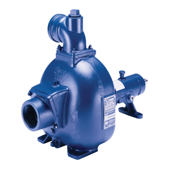
See Figure 1 and 2 for the approximate physical di configuration, and priming must be tailored to the mensions of this pump. OUTLINE DRAWING Figure 1. Pump Model 83A3-B PREINSTALLATION INSPECTION b. Check for and tighten loose attaching hard ware. Since gaskets tend to shrink after dry... -
Page 9: Positioning Pump
OM-00862 80 SERIES Only operate this pump in the direction in The pump assembly can be seriously dicated by the arrow on the pump body damaged if the cables or chains used to lift and on the accompanying decal. Other and move the unit are improperly wrapped wise, the impeller could become loosened around the pump. -
Page 10: Gauges
80 SERIES OM-00862 cause excessive vibration, decreased bearing life, This pump is designed to handle up to 3/4-inch and increased shaft and seal wear. If hose‐type (19,1 mm) diameter spherical solids. lines are used, they should have adequate support to secure them when filled with liquid and under Sealing pressure. -
Page 11: Discharge Lines
OM-00862 80 SERIES reduce the inlet velocity. Calculate the required on the increased opening size (area or diameter). submergence using the following formula based Figure 2. Recommended Minimum Suction Line Submergence vs. Velocity DISCHARGE LINES Siphoning If the application involves a high discharge head, gradually close the discharge Do not terminate the discharge line at a level lower throttling valve before stopping the pump. -
Page 12: Coupled Drives
80 SERIES OM-00862 either a flexible coupling or V‐belt driven system, ends are the same distance apart at all points (see the driver and pump must be mounted so that their Figure 3A). shafts are aligned with and parallel to each other. It is imperative that alignment be checked after the pump and piping are installed, and before opera... -
Page 13: General Rules Of Tensioning
OM-00862 80 SERIES from dirt, grease, oil and other foreign material which may cause slippage. Tension Measurement Correct v‐belt tension can be achieved using a v‐ belt tension tester and Table 1 or 2. Use the tables to find the v‐belt size (cross‐section), the smallest sheave diameter, the belt type for your application. - Page 14 80 SERIES OM-00862 Place the tension tester squarely on the belt at the O‐ring on the deflection force scale. Compare this center of the belt span. Apply force on the plunger, force with the value shown in Table 1 or 2 and ad perpendicular to the belt span, until the bottom of just the tension accordingly.
- Page 15 OM-00862 80 SERIES Table 1. Sheave Diameter (Inches) Table 2. Sheave Diameter (Millimeters) Deflection Force (Lbs.) Deflection Force (KG.) Belt Deflection Force Belt Deflection Force Uncogged Cogged Uncogged Cogged Hy‐T Belts & Torque‐Flex Hy‐T Belts & Torque‐Flex Uncogged & Machined Uncogged &...
-
Page 16: Operation - Section C
OM-00862 80 SERIES OPERATION - SECTION C Review all SAFETY information in Section A. PRIMING Follow the instructions on all tags, labels and Install the pump and piping as described in IN decals attached to the pump. STALLATION. Make sure that the piping connec tions are tight, and that the pump is securely mounted. -
Page 17: Starting
OM-00862 80 SERIES STARTING OPERATION Lines With a Bypass Consult the operations manual furnished with the power source. Close the discharge throttling valve (if so equipped) so that the pump will not have to prime If the pump has been approved for use with petro against the weight of the liquid in the discharge line. -
Page 18: Strainer Check
OM-00862 80 SERIES boil, build pressure, and cause the pump to rup lift, and should then stabilize. If the vacuum reading ture or explode. If overheating occurs, stop the falls off rapidly after stabilization, an air leak exists. pump and allow it to completely cool before servic Before checking for the source of the leak, check the point of installation of the vacuum gauge. - Page 19 OM-00862 80 SERIES curately by placing a contact‐type thermometer rect level (see LUBRICATION in Section E). Bear against the housing. Record this temperature for ing overheating can also be caused by shaft future reference. misalignment and/or excessive vibration. A sudden increase in bearing temperatures is a When pumps are first started, the bearings may warning that the bearings are at the point of failing seem to run at temperatures above normal.
- Page 20 80 SERIES OM-00862 TROUBLESHOOTING - SECTION D Review all SAFETY information in Section A. Before attempting to open or service the pump: 1. Familiarize yourself with this man ual. 2. Lock out or disconnect the power source to ensure that the pump will remain inoperative.
- Page 21 OM-00862 80 SERIES TROUBLE POSSIBLE CAUSE PROBABLE REMEDY Impeller or other wearing parts worn Replace worn or damaged parts. PUMP STOPS OR FAILS TO DELIVER or damaged. Check that impeller is properly RATED FLOW OR centered and rotates freely. PRESSURE (cont.) Impeller clogged.
- Page 22 80 SERIES OM-00862 equipped) between regularly scheduled inspec PREVENTIVE MAINTENANCE tions can indicate problems that can be corrected Since pump applications are seldom identical, and before system damage or catastrophic failure oc pump wear is directly affected by such things as curs.
- Page 23 PUMP MAINTENANCE AND REPAIR - SECTION E MAINTENANCE AND REPAIR OF THE WEARING PARTS OF THE PUMP WILL MAINTAIN PEAK OPERATING PERFORMANCE. STANDARD PERFORMANCE FOR PUMP MODEL 83A3-B Based on 70_ F (21_ C) clear water at sea level Contact the Gorman‐Rupp Company to verify per...
- Page 24 OM-00862 80 SERIES SECTION DRAWING PARTS PAGE Figure 1. Pump Model 83A3-B PAGE E - 2 MAINTENANCE & REPAIR...
- Page 25 OM-00862 80 SERIES PARTS LIST Pump Model 83A3-B (From S/N 734045 up) If your pump serial number is followed by an “N”, your pump is NOT a standard production model. Contact the Gorman‐Rupp Company to verify part numbers. ITEM PART NAME...
- Page 26 Before attempting to open or service the Use Only Genuine Gorman-Rupp re pump: placement parts. Failure to do so may cre 1. Familiarize yourself with this man...
- Page 27 80 SERIES OM-00862 to separate the casing from the seal plate and ped such hazard, damage or diminished per estal. formance is not covered by the warranty. NOTE When appropriate recycling facilities are available, the user should recycle components and fluids when doing any routine maintenance / repairs and Do not attempt to lift the complete pump also at the end of the pump’s useful life.
- Page 28 OM-00862 80 SERIES Shaft And Bearing Removal And Disassembly Turn Counterclockwise When the pump is properly operated and main tained, the pedestal should not require disassem bly. Disassemble the shaft and bearings only when there is evidence of wear or damage. Lathe Dog Arm “V”...
- Page 29 80 SERIES OM-00862 If bearing replacement is required, use a bearing the shaft, it is recommended that bearings puller to remove the inboard and outboard bear be cleaned and inspected in place. It is ings from the impeller shaft. strongly recommended that the bearings be replaced any time the shaft and bear...
- Page 30 OM-00862 80 SERIES If heating the bearings is not practical, use a suit Seal Reassembly and Installation ably sized sleeve and an arbor (or hydraulic) press (Figures 1 and 3) to install the bearings on the shaft. Clean the seal cavity and shaft with a cloth soaked in fresh cleaning solvent.
- Page 31 80 SERIES OM-00862 ROTATING STATIONARY SPRING ELEMENT SEAT STATIONARY IMPELLER ELEMENT IMPELLER IMPELLER SHAFT ADJUSTING SHIMS SHAFT SLEEVE SEAL PLATE SPRING SEAT BELLOWS RETAINER Figure 3. Seal Assembly Slide the assembled seal and shaft sleeve onto the shaft until the seal faces contact. Continue to push the sleeve through the seal until the chamfered end seats firmly against the shaft shoulder.
- Page 32 OM-00862 80 SERIES After the back clearance is set, secure the impeller 45) to the check valve gasket (44) with the hard with the hardware (31, 32 and 33). ware (46 and 47). Position the check valve assembly in the suction Pump Casing Installation port with the large weight (45) facing toward the in...
- Page 33 80 SERIES OM-00862 NOTE cant regularly for evidence of rust or mois ture condensation. This is especially im The white reflector in the sight gauge must be posi portant in areas where variable hot and tioned horizontally to provide proper drainage. cold temperatures are common.
- Page 34 For Warranty Information, Please Visit www.grpumps.com/warranty or call: U.S.: 419-755-1280 Canada: 519-631-2870 International: +1-419-755-1352 GORMAN‐RUPP PUMPS...
Need help?
Do you have a question about the 83A3-B and is the answer not in the manual?
Questions and answers