GORMAN-RUPP 80 Series Installation, Operation, And Maintenance Manual With Parts List
Hide thumbs
Also See for 80 Series:
Table of Contents
Advertisement
Quick Links
ACE
OM‐02398‐01
May 29, 1985
Rev. C 12‐19‐12
INSTALLATION, OPERATION,
AND MAINTENANCE MANUAL
WITH PARTS LIST
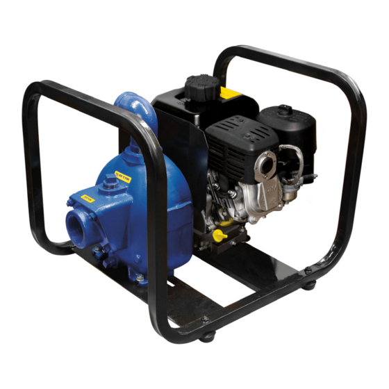
80 SERIES PUMP
MODEL
810A2‐B
THE GORMAN‐RUPP COMPANY D MANSFIELD, OHIO
www.grpumps.com
D
GORMAN‐RUPP OF CANADA LIMITED
ST. THOMAS, ONTARIO, CANADA
Printed in U.S.A.
e
1985 The Gorman‐Rupp Company
Advertisement
Table of Contents

Related Manuals for GORMAN-RUPP 80 Series


Summary of Contents for GORMAN-RUPP 80 Series
- Page 1 OM‐02398‐01 May 29, 1985 Rev. C 12‐19‐12 INSTALLATION, OPERATION, AND MAINTENANCE MANUAL WITH PARTS LIST 80 SERIES PUMP MODEL 810A2‐B THE GORMAN‐RUPP COMPANY D MANSFIELD, OHIO www.grpumps.com GORMAN‐RUPP OF CANADA LIMITED ST. THOMAS, ONTARIO, CANADA Printed in U.S.A. 1985 The Gorman‐Rupp Company...
- Page 2 Register your new Gorman‐Rupp pump online at www.grpumps.com Valid serial number and e‐mail address required. RECORD YOUR PUMP MODEL AND SERIAL NUMBER Please record your pump model and serial number in the spaces provided below. Your Gorman‐Rupp distributor needs this information when you require parts or service. Pump Model: Serial Number:...
-
Page 3: Table Of Contents
TABLE OF CONTENTS INTRODUCTION ..........PAGE I - 1 SAFETY ‐... - Page 4 TABLE OF CONTENTS (continued) PUMP MAINTENANCE AND REPAIR ‐ SECTION E ....PAGE E - 1 STANDARD PERFORMANCE CURVE ........PAGE E - 1 PARTS LIST: Pump Model...
-
Page 5: Introduction
Gorman‐ Rupp pump. This pump is an 80 Series, semi‐open impeller, self‐ priming centrifugal model with a suction check Immediate hazards which WILL result in valve. -
Page 6: Safety - Section A
80 SERIES OM-02398 SAFETY ‐ SECTION A This information applies to 80 Series ba non‐volatile, non‐flammable liquids containing specified entrained solids. sic pumps. Gorman‐Rupp has no con Do not attempt to pump liquids for trol over or particular knowledge of the which the pump, driver and/or controls power source which will be used. - Page 7 OM-02398 80 SERIES Overheated pumps can cause severe Never run this pump backwards. Be cer burns and injuries. If overheating of the tain that rotation is correct before fully pump occurs: engaging the pump. 1. Stop the pump immediately. 2. Ventilate the area.
-
Page 8: Installation - Section B
80 SERIES OM-02398 INSTALLATION - SECTION B Review all SAFETY information in Section A. configuration, and priming must be tailored to the specific application. This pump is equipped with a Since pump installations are seldom identical, this Gorman‐Rupp double grease lubricated seal,... -
Page 9: Positioning Pump
OM-02398 80 SERIES The pump assembly can be seriously Only operate this pump in the direction in damaged if the cables or chains used to lift dicated by the arrow on the pump body and move the unit are improperly wrapped and on the accompanying decal. -
Page 10: Gauges
80 SERIES OM-02398 Lines near the pump must be independently sup line, and that the openings will not permit passage ported to avoid strain on the pump which could of solids larger than the solids handling capability cause excessive vibration, decreased bearing life, of the pump. -
Page 11: Discharge Lines
OM-02398 80 SERIES reduce the inlet velocity. Calculate the required NOTE submergence using the following formula based The pipe submergence required may be reduced on the increased opening size (area or diameter). by installing a standard pipe increaser fitting at the end of the suction line. -
Page 12: Alignment
80 SERIES OM-02398 of the outer ends of the coupling hub every 90 ALIGNMENT The coupling is in alignment when the hub ends are the same distance apart at all points (see Fig The alignment of the pump and its power source is ure 3A). -
Page 13: V-Belt Tensioning
OM-02398 80 SERIES the belts are a matched set; unmatched sets will en both v‐belt and bearing life. Under‐tensioning cause accelerated belt wear. will cause belt slippage. Always keep belts free from dirt, grease, oil and other foreign material which may cause slippage. - Page 14 80 SERIES OM-02398 er at the measured belt span. Set the small O‐ring Read the force applied from the bottom of the small on the deflection force scale to zero. O‐ring on the deflection force scale. Compare this force with the value shown in Table 1 or 2 and ad...
- Page 15 OM-02398 80 SERIES Table 1. Sheave Diameter (Inches) Table 2. Sheave Diameter (Millimeters) Deflection Force (Lbs.) Deflection Force (KG.) Belt Deflection Force Belt Deflection Force Uncogged Cogged Uncogged Cogged Hy‐T Belts & Torque‐Flex Hy‐T Belts & Torque‐Flex Uncogged & Machined Uncogged &...
-
Page 16: Operation - Section C
OM-02398 80 SERIES OPERATION - SECTION C Review all SAFETY information in Section A. Add liquid to the pump casing when: 1. The pump is being put into service for the Follow the instructions on all tags, labels and first time. -
Page 17: Operation
OM-02398 80 SERIES sprinkler heads, and any other fixtures connected from the shaft and seriously damage the to the line. When the discharge line is completely pump. filled, adjust the throttling valve to the required flow Consult the operating manual furnished with the rate. -
Page 18: Pump Vacuum Check
OM-02398 80 SERIES equipment. If backflushing is absolutely neces Cold Weather Preservation sary, liquid pressure must be limited to 50% of the In below freezing conditions, drain the pump to maximum permissible operating pressure shown prevent damage from freezing. Also, clean out any on the pump performance curve (see Section E, solids by flushing with a hose. -
Page 19: Troubleshooting - Section D
80 SERIES OM-02398 TROUBLESHOOTING - SECTION D Review all SAFETY information in Section A. Before attempting to open or service the pump: 1. Familiarize yourself with this man ual. 2. Lock out or disconnect the power source to ensure that the pump will remain inoperative. - Page 20 OM-02398 80 SERIES TROUBLE POSSIBLE CAUSE PROBABLE REMEDY Impeller or other wearing parts worn Replace worn or damaged parts. PUMP STOPS OR FAILS TO DELIVER or damaged. Check that impeller is properly RATED FLOW OR centered and rotates freely. PRESSURE (cont.) Impeller clogged.
-
Page 21: Preventive Maintenance
80 SERIES OM-02398 equipped) between regularly scheduled inspec PREVENTIVE MAINTENANCE tions can indicate problems that can be corrected Since pump applications are seldom identical, and before system damage or catastrophic failure oc pump wear is directly affected by such things as curs. - Page 22 OM-02398 80 SERIES PUMP MAINTENANCE AND REPAIR - SECTION E MAINTENANCE AND REPAIR OF THE WEARING PARTS OF THE PUMP WILL MAINTAIN PEAK OPERATING PERFORMANCE. STANDARD PERFORMANCE FOR PUMP MODEL 810A2-B Based on 70 F (21 C) clear water at sea level Contact the Gorman‐Rupp Company to verify per...
- Page 23 80 SERIES OM-02398 SECTION DRAWING PARTS PAGE DRIVE END VIEW Figure 1. Pump Model 810A2-B PAGE E - 2 MAINTENANCE & REPAIR...
- Page 24 OM-02398 80 SERIES PARTS LIST Pump Model 810A2‐B (From S/N 819132 Up) If your pump serial number is followed by an “N”, your pump is NOT a standard production model. Contact the Gorman‐Rupp Company to verify part numbers. ITEM PART NAME...
- Page 25 80 SERIES OM-02398 PUMP AND SEAL DISASSEMBLY 4. Check the temperature before opening any covers, plates, or AND REASSEMBLY plugs. 5. Close the suction and discharge Review all SAFETY information in Section A. valves. 6. Vent the pump slowly and cau...
- Page 26 OM-02398 80 SERIES wise until it rests against the cover (see Figure 4) to measure and record their thickness for ease of prevent the grease in the cup from escaping. Re reassembly. move the grease cup and piping (18, 19, 20, 21 and 22).
- Page 27 80 SERIES OM-02398 screwdrivers against the heads of the machine screws. After removing the bearing retainer, tight en the machine screws. Bearings must be kept free of all dirt and Press the oil seal (34) from the bearing retainer, and remove the O‐ring (28) from the pedestal bore.
- Page 28 OM-02398 80 SERIES NOTE Install a new O‐ring (41) in the groove in the bear ing cap. Slide the assembled bearing cap and oil Install the inboard bearing (24) with the integral re seal over the shaft until fully seated against the taining ring on the O.D.
- Page 29 80 SERIES OM-02398 gency, carefully wash all metallic parts in fresh if there are nicks or cuts on either end. If any com cleaning solvent and allow to dry thoroughly. ponents are worn, replace the complete seal; never mix old and new seal parts.
- Page 30 OM-02398 80 SERIES Before installing the seal, lubricate the seal liner the shaft until tight. Make sure the seal spring seats with water or a very small amount of oil, and apply squarely over the step on the back of the impeller.
- Page 31 80 SERIES OM-02398 Before starting the pump, fill the pump casing with LUBRICATION clean liquid. Apply “Never‐Seez” or equivalent compound to the fill plug (7). Reinstall and tighten Seal Assembly the fill plug. Fill the grease cup (18) through the grease fitting with No.
- Page 32 For U.S. and International Warranty Information, Please Visit www.grpumps.com/warranty or call: U.S.: 419-755-1280 International: +1-419-755-1352 For Canadian Warranty Information, Please Visit www.grcanada.com/warranty or call: 519-631-2870 THE GORMAN‐RUPP COMPANY D MANSFIELD, OHIO GORMAN‐RUPP OF CANADA LIMITED ST. THOMAS, ONTARIO, CANADA...
Need help?
Do you have a question about the 80 Series and is the answer not in the manual?
Questions and answers