GORMAN-RUPP 80 SERIES Installation, Operation And Maintenance Manual
Hide thumbs
Also See for 80 SERIES:

Subscribe to Our Youtube Channel
Related Manuals for GORMAN-RUPP 80 SERIES


Summary of Contents for GORMAN-RUPP 80 SERIES
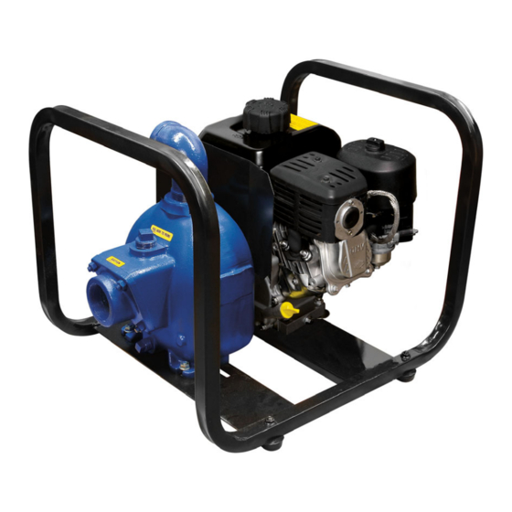
- Page 1 OM-07163-01 February 23, 2018 Rev. A - 12/17/18 INSTALLATION, OPERATION, AND MAINTENANCE MANUAL WITH PARTS LIST 80 SERIES PUMP MODEL 82D1-XR550-X GORMAN‐RUPP PUMPS www.grpumps.com 2018 Gorman‐Rupp Pumps Printed in U.S.A.
- Page 2 Register your new Gorman‐Rupp pump online at www.grpumps.com Valid serial number and e‐mail address required. The engine exhaust from this product contains chemicals known to the State of California to cause cancer, birth defects or other reproductive harm. RECORD YOUR PUMP MODEL AND SERIAL NUMBER Please record your pump model and serial number in the spaces provided below.
-
Page 3: Table Of Contents
TABLE OF CONTENTS INTRODUCTION ..........PAGE I - 1 SAFETY ‐... - Page 4 TABLE OF CONTENTS (continued) PARTS LISTS: Pump Model ............PAGE E - 3 Pump Parts Only .
-
Page 5: Introduction
80 SERIES OM-07163 INTRODUCTION Thank You for purchasing a Gorman‐Rupp pump. HAZARD AND INSTRUCTION Read this manual carefully to learn how to safely DEFINITIONS install and operate your pump. Failure to do so could result in personal injury or damage to the The following are used to alert maintenance per... -
Page 6: Safety - Section A
80 SERIES OM-07163 SAFETY ‐ SECTION A This information applies to 80 Series en gine driven pumps. Refer to the manual accompanying the engine before at tempting to begin operation. This pump is designed to handle water, gasoline and other petroleum products in a non‐flammable atmosphere. - Page 7 OM-07163 80 SERIES Do not operate an internal combustion Do not operate the pump against a engine in an explosive atmosphere. closed discharge valve for long periods When operating internal combustion of time. If operated against a closed dis engines in an enclosed area, make cer...
-
Page 8: Installation - Section B
80 SERIES OM-07163 INSTALLATION - SECTION B Review all SAFETY information in Section A. specific application. Since the pressure supplied to the pump is critical to performance and safety, Since pump installations are seldom identical, this be sure to limit the incoming pressure to 50% of the... -
Page 9: Positioning Pump
OM-07163 80 SERIES ing, check for loose hardware at mating sur Mounting faces. Locate the pump in an accessible place as close as practical to the liquid being pumped. Level mount c. Carefully read all tags, decals, and markings ing is essential for proper operation. -
Page 10: Gauges
80 SERIES OM-07163 place by tightening the flange bolts and/or cou total area of the openings in the strainer is at least plings. three or four times the cross section of the suction line, and that the openings will not permit passage Lines near the pump must be independently sup... -
Page 11: Discharge Lines
OM-07163 80 SERIES reduce the inlet velocity. Calculate the required NOTE submergence using the following formula based The pipe submergence required may be reduced on the increased opening size (area or diameter). by installing a standard pipe increaser fitting at the end of the suction line. -
Page 12: Grounding
80 SERIES OM-07163 GROUNDING To eliminate electrostatic build‐up by the liquid be ing pumped, the unit must be grounded by attach Inspect and test the ground wire assembly ing the ground wire assembly to a ground rod. In stall the ground rod in accordance with the Nation... -
Page 13: Operation - Section C
OM-07163 80 SERIES OPERATION - SECTION C Review all SAFETY information in Section A. not prime when dry. Extended operation of a dry pump will destroy the seal assembly. Follow the instructions on all tags, labels and decals attached to the pump. -
Page 14: Operation
OM-07163 80 SERIES pump and allow it to cool before servicing it. Refill OPERATION the pump casing with cool liquid. Lines With a Bypass Close the discharge throttling valve (if so equipped) so that the pump will not have to prime... -
Page 15: Stopping
OM-07163 80 SERIES immediately drop proportionate to static suction lift, and should then stabilize. If the vacuum reading falls off rapidly after stabilization, an air leak exists. Before checking for the source of the leak, check If the application involves a high discharge the point of installation of the vacuum gauge. -
Page 16: Troubleshooting - Section D
80 SERIES OM-07163 TROUBLESHOOTING - SECTION D Review all SAFETY information in Section A. Before attempting to open or service the pump: 1. Familiarize yourself with this manual. 2. Shut down the engine and take pre cautions to ensure that the pump will remain inoperative. - Page 17 OM-07163 80 SERIES TROUBLE POSSIBLE CAUSE PROBABLE REMEDY Air leak in suction line. Correct leak. PUMP STOPS OR FAILS TO DELIVER Lining of suction hose collapsed. Replace suction hose. RATED FLOW OR Suction intake not submerged at Check installation and correct PRESSURE (cont.)
-
Page 18: Preventive Maintenance
80 SERIES OM-07163 equipped) between regularly scheduled inspec PREVENTIVE MAINTENANCE tions can indicate problems that can be corrected Since pump applications are seldom identical, and before system damage or catastrophic failure oc pump wear is directly affected by such things as curs. -
Page 19: Pump Maintenance And Repair - Section E
80 SERIES OM-07163 PUMP MAINTENANCE AND REPAIR ‐ SECTION E MAINTENANCE AND REPAIR OF THE WEARING PARTS OF THE PUMP WILL MAINTAIN PEAK OPERATING PERFORMANCE. STANDARD PERFORMANCE FOR PUMP MODEL 82D1‐XR550‐X Based on 70_ F (21_ C) clear water (corrected to Contact the Gorman‐Rupp Company to verify per... - Page 20 OM-07163 80 SERIES PARTS PAGE ILLUSTRATION Figure 1. Pump Model 82D1‐XR550‐X PAGE E - 2 MAINTENANCE & REPAIR...
- Page 21 80 SERIES OM-07163 PARTS LIST 82D1‐XR550‐X Pump Model (From S/N 1665138 Up) If your pump serial number is followed by an “N”, your pump is NOT a standard production model. Contact the Gorman‐Rupp Company to verify part numbers. ITEM PART...
- Page 22 OM-07163 80 SERIES ILLUSTRATION SEAL AREA DETAIL Figure 2. Pump Parts PAGE E - 4 MAINTENANCE & REPAIR...
- Page 23 80 SERIES OM-07163 PARTS LIST Pump Parts ITEM PART PART NAME NUMBER PUMP CASING 6846C 13040 FILL PLUG ASSY 48271-062 STREET ELBOW RS32 11999 STUD C0606 15991 HEX HEAD CAP SCREW B0503-1/2S 15991 LOCK WASHER J05 15991 HEX NUT D06 15991...
- Page 24 OM-07163 80 SERIES ILLUSTRATION DETAIL A AIR CLEANER ASSEMBLY REMOVED Figure 3. Engine Modification Assembly PAGE E - 6 MAINTENANCE & REPAIR...
- Page 25 80 SERIES OM-07163 PARTS LIST Engine Modification Assembly ITEM PART PART NAME NUMBER BRIGGS XR550 ENGINE 29112-401 SHIELDED SPARK PLUG 29331-078 SHIELDED LEAD ASSY 29172-231 SPRING PLUNGER 29184-003 HEX NUT D#08 17000 INSULATOR 29172-232 FLAT HEAD CAP SCREW MF0516 17000...
- Page 26 Close all valves in the suction and discharge lines. Use Only Genuine Gorman-Rupp re placement parts. Failure to do so may cre For engine disassembly and repair, consult the lit...
- Page 27 80 SERIES OM-07163 (Figure 2) Remove the nuts (7) securing the pump casing to the intermediate. Separate the parts by pulling the casing straight away from the intermediate. If Before attempting to open or service the shims have been used under the mounting feet to pump: level the pump casing, tie and tag these shims.
- Page 28 OM-07163 80 SERIES If no further disassembly is required, see Seal during reassembly. This could result in premature Reassembly and Installation. failure. If necessary to reuse an old seal in an emer gency, carefully wash all metallic parts in fresh Seal Reassembly and Installation cleaning solvent and allow to dry thoroughly.
- Page 29 80 SERIES OM-07163 SPRING INTERMEDIATE RETAINER SPRING CENTERING ROTATING WASHER ELEMENT O‐RING IMPELLER ENGINE CRANKSHAFT SEAL SLEEVE IMPELLER SHIMS STATIONARY DRIVE BAND BELLOWS SEAT Figure 4. Seal Assembly NOTE If the intermediate was not separated from the en gine during disassembly, subassemble the O‐ring...
- Page 30 OM-07163 80 SERIES Impeller Installation And Adjustment Position the check valve assembly (20) in the suc tion port with the large weight toward the inside of (Figure 2) the pump. Install the suction flange (19) and se cure with the nuts (7). Check the operation of the...
- Page 31 For Warranty Information, Please Visit www.grpumps.com/warranty or call: U.S.: 419-755-1280 Canada: 519-631-2870 International: +1-419-755-1352 GORMAN‐RUPP PUMPS...
Need help?
Do you have a question about the 80 SERIES and is the answer not in the manual?
Questions and answers