Advertisement
Quick Links
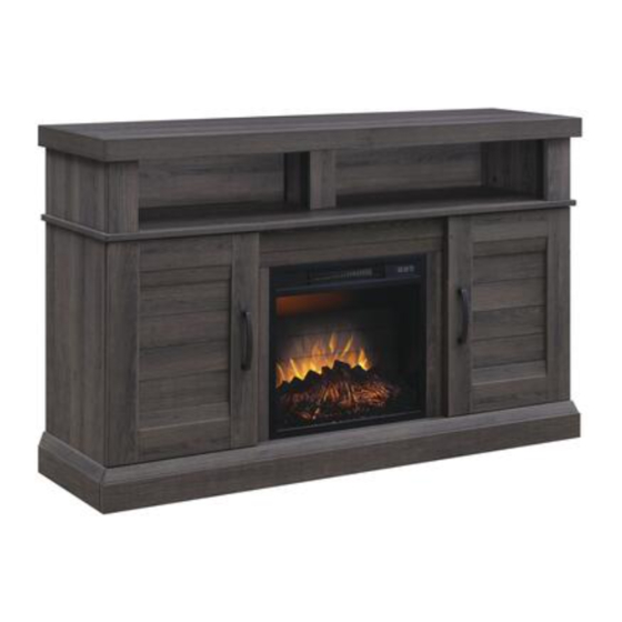
Ashton 54" Fireplace Console
If you have any questions regarding assembly or if parts are missing, DO NOT return this item to the
store where it was purchased. Please call our toll-free customer service number and have your
instructions and parts list ready to provide the model name, part name or factory number:
Or visit our website 24 Hours a day, 7 days a week for product assistance at
THIS INSTRUCTION BOOKLET CONTAINS IMPORTANT SAFETY INFORMATION.
Model # MNFP54AS-18
ADULT ASSEMBLY REQUIRED
Pacific Standard Time: 8:30 a.m. - 4:30 p.m., Monday - Friday
www.whalenfurniture.com
Or e-mail your request to:
PLEASE READ AND KEEP FOR FUTURE REFERENCE.
Date 2020-06-08
OR
1-866-942-5362
parts@whalenfurniture.com
Rev. 0001-A
LOT NUMBER:
DATE PURCHASED: /
/
Advertisement

Related Manuals for Whalen Ashton MNFP54AS-18


Summary of Contents for Whalen Ashton MNFP54AS-18
- Page 1 LOT NUMBER: DATE PURCHASED: / Ashton 54" Fireplace Console Model # MNFP54AS-18 ADULT ASSEMBLY REQUIRED If you have any questions regarding assembly or if parts are missing, DO NOT return this item to the store where it was purchased. Please call our toll-free customer service number and have your instructions and parts list ready to provide the model name, part name or factory number: 1-866-942-5362 Pacific Standard Time: 8:30 a.m.
- Page 2 M A X I M U M R E C O M M E N D E D W E I G H T L O A D S MANUFACTURER: Whalen Furniture Manufacturing CATALOG: Ashton 54" Fireplace Console MODEL # MNFP54AS-18 FITS UP TO MOST 165.1 cm (65 in.)
- Page 3 IMPORTANT Before you begin: Open, identify and count all parts prior to assembly. Lay out parts on a flat and non- abrasive surface. You will need the parts identified on page 4 and 5 of this instruction manual. NOTE: IT IS VERY IMPORTANT TO USE GLUE WITH THE DOWELS. EXCESS GLUE CAN BE WIPED OFF WITH A DAMP CLOTH.
-
Page 4: Parts And Hardware List
Parts and Hardware List Please read completely through the instructions and verify that all listed parts and hardware are present before beginning assembly. A- Top Panel (Qty. 1) B- Center Shelf (Qty. 1) C- Bottom Panel (Qty. 1) D- Left Lower Side Panel E- Right Lower Side Panel F- Left Lower Partition Panel (Qty. - Page 5 Parts and Hardware List Please read completely through the instructions and verify that all listed parts and hardware are present before beginning assembly. (1) Cam Lock (2) Cam Bolt (3) M8 x 30 mm Wood Dowel (Qty. 48+2 extra) (Qty. 48+2 extra) (Qty.
- Page 6 Assembly Instructions 1. Unpack the unit and confirm that you have all the hardware and required parts. Assemble the unit on a carpeted floor or the empty carton to avoid any scratches. 2. Securely screw the Cam Bolts (2) into the designated small holes on the Top Panel (A), Center Shelf (B) and Bottom Panel (C) using a Phillips screwdriver.
- Page 7 Assembly Instructions 4. Glue the Wood Dowels (3) into the side holes of the Panels (D, E, F and G). 5. Glue the Wood Dowels (3) into the side holes of the Middle Crossbar (L), Middle Stiles (M), Bottom Back Stretcher (N) and Bottom Front Molding (O).
- Page 8 Assembly Instructions 6. Glue the Wood Dowels (3) into the side holes of the Panels (H and J) and Upper Side Panel Moldings (I). 7. Securely screw the Cam Bolts (2) into the designated small holes on the Moldings (I and K) using a Phillips screwdriver.
- Page 9 Assembly Instructions 11. Attach the Middle Crossbar (L) to the Center Shelf (B) by engaging three Cam Locks (1). 12. Attach the Bottom Back Stretcher (N) to the Bottom Panel (C) by engaging three Cam Locks (1).
- Page 10 Assembly Instructions 13. Attach the Bottom Front Molding (O) to the Bottom Panel (C) by engaging four Cam Locks (1). 14. Attach the Middle Stiles (M) to the Lower Partition Panels (F and G) by engaging the Cam Locks (1).
- Page 11 Assembly Instructions 15. Attach the Lower Partition Panels (F and G) to the Bottom Panel (C) with four 50 mm Screws (7). 16. Align the large holes on both Side Panels (D and E) with the inserted Wood Dowels (1) and press them together.
- Page 12 Assembly Instructions 17. Ask for assistance to place the Center Shelf (B) onto the inserted wood dowels on the vertical panels (D, E, F and G) properly and fasten it in place with the Cam Locks (1). 18. Using the pilot holes as a guide, fasten two Triangle Metal Plates (8) at the bottom joints between the Bottom Front Molding (O) and Lower Side Panels (D and E) using four 15 mm Pan Head Screws (6) per plate.
- Page 13 Assembly Instructions 19. Screw two Floor Levelers (9) into the installed Triangle Metal Plates (8). 20. Stand the assembled unit upright. 21. Securely screw the Cam Bolts (2) into the designated small holes on the Center Shelf (B) using a Phillips screwdriver.
- Page 14 Assembly Instructions H/ I /J 22. Attach both upper side panel assemblies and Partition Panel (J) to the Center Shelf (B) by engaging the Cam Locks (1). H/ I /J 23. Position the Top Panel (A) onto the inserted Wood Dowels (1) and fasten it in place by engaging six Cam Locks (1).
- Page 15 Assembly Instructions 24. Ask for assistance to lay down the assembled unit at its front edges. 25. Using the pilot holes as a guide, attach two Straight Metal Brackets (10) at the joints where the Middle Crossbar (L) meets the Middle Stiles (M) with four 12 mm Flat Head Screws (4). 26.
- Page 16 Assembly Instructions 28. Stand the assembled unit upright. 29. Pick up one Door (Q) and attach the extended hinge arms to the hinge bases installed on the Left Lower Side Panel (D). Loosen the bolt on the back of the hinge base for an easy fit. Align and insert the “U” slot on the hinge arm under the bolt head on the back of the hinge base.
- Page 17 Assembly Instructions 33. Open the Doors (Q) and insert four Shelf Supports (13) into the desired holes inside each side compartment. Make sure you place the four shelf supports in the same level so the shelf is not tilted. Rest the adjustable Shelves (P) onto the Shelf Supports (13).
- Page 18 Assembly Instructions 36. Unpack the fireplace insert from the inner box and follow the instructions to install the Top Trim and Side Trims to the fireplace insert. 37. Lift the fireplace insert carefully into the back of the assembled mantel and center it in the opening. DO NOT drag the insert across the Bottom Panel (C) as it may scratch the unit.
- Page 19 Assembly Instructions NOTE: The door panels with groove are pre-attached when shipping. You can keep as is or interchange as the desired configuration. 41. To change door panels, loosen the screws on the inside of the door and rotate the clips to remove the panel. Replace with the desired panel, then rotate clips to secure the panel within the door frame and tighten screws.
- Page 20 Assembly Instructions Tools required: Phillips screwdriver, stud finder, power drill and 1/8” drill bit. 42. Ask for assistance to position the assembled fireplace at the desired location against a wall. If necessary, adjust the installed Floor Levelers at the bottom of the Base to level the unit. Now, follow the instructions printed on the plastic bag containing the Tipping Restraint Hardware to attach the tip-over restraints to the unit and the wall.
-
Page 21: Care And Maintenance
Should this product be defective in workmanship or materials or fail under normal use, we will repair or replace it for up to one (1) year from date of purchase. Every Whalen Furniture product is designed to meet your highest expectations. We guarantee that you will immediately see the value of our fine furniture.
Need help?
Do you have a question about the Ashton MNFP54AS-18 and is the answer not in the manual?
Questions and answers