Advertisement
Available languages
Available languages
Quick Links
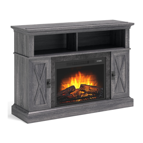
Kellum Media Fireplace Console
If you have any questions regarding assembly or if parts are missing, DO NOT return this item to the
store where it was purchased. Please call our customer service number and have your instructions
and parts list ready to provide the model name, part name or factory number:
Pacific Standard Time: 8:30 a.m. - 4:30 p.m., Monday - Friday
Or visit our web site 24 hours a day, 7 days a week for product assistance at
THIS INSTRUCTION BOOKLET CONTAINS IMPORTANT SAFETY INFORMATION.
Stock # WMFP48EC-26GR
# WMFP48EC-26BR
ADULT ASSEMBLY REQUIRED
www.whalenstyle.com
Or e-mail your request to parts@whalenfurniture.com
PLEASE READ AND KEEP FOR FUTURE REFERENCE.
Date 2020-07-10
866-942-5362
Rev. 0001-A
LOT NUMBER:
DATE PURCHASED:
/
/
Advertisement

Related Manuals for Whalen Kellum WMFP48EC-26GR


Summary of Contents for Whalen Kellum WMFP48EC-26GR
- Page 1 LOT NUMBER: DATE PURCHASED: Kellum Media Fireplace Console Stock # WMFP48EC-26GR # WMFP48EC-26BR ADULT ASSEMBLY REQUIRED If you have any questions regarding assembly or if parts are missing, DO NOT return this item to the store where it was purchased. Please call our customer service number and have your instructions and parts list ready to provide the model name, part name or factory number: 866-942-5362 Pacific Standard Time: 8:30 a.m.
- Page 2 M A X I M U M R E C O M M E N D E D W E I G H T L O A D S MANUFACTURER: Whalen Furniture Manufacturing CATALOG: Kellum Media Fireplace Console MODEL # WMFP48EC-26BR / WMFP48EC-26GR FITS UP TO MOST 58”...
- Page 3 IMPORTANT Before you begin: Open, identify and count all parts prior to assembly. Lay out parts on a flat and non- abrasive surface. You will need the parts identified on page 4 and 5 of this instruction manual. NOTE: IT IS VERY IMPORTANT TO USE GLUE WITH DOWELS. EXCESS GLUE CAN BE WIPED OFF WITH DAMP CLOTH.
-
Page 4: Parts And Hardware List
Parts and Hardware List Please read completely through the instructions and verify that all listed parts and hardware are present before beginning assembly. A- Top Panel ( B- Upper Side Panel ( C- Upper Front Panel ( Qty. 1 Qty. 2 Qty. - Page 5 Parts and Hardware List Please read completely through the instructions and verify that all listed parts and hardware are present before beginning assembly. Qty. 1 T- Stop Rail ( Fireplace Insert (Qty. 1) Remote Control with Battery (Qty. 1) (1) Cam Lock (2) Cam Bolt (3) M8 x 30 mm Wood Dowel (Qty.
- Page 6 Assembly Instructions ② x 26 NOTE: Please do not fully tighten all bolts until you finish assembling all parts. Once assembled, go back and fully tighten all bolts. This will make it easier during assembly of unit. 1. Unpack the unit and confirm that you have all the hardware and required parts. Assemble the unit on a carpeted floor or the empty carton to avoid any scratch.
- Page 7 Assembly Instructions ② x 17 3. Securely screw seventeen Cam Bolts (2) into the designated small holes on the Center Shelf (E) on both sides.
- Page 8 Assembly Instructions ② x 8 4. Securely screw the Cam Bolts (2) into the designated small holes on the Lower Partition Panels (H and I) at both sides.
- Page 9 Assembly Instructions ③ x 2 ① x 3 5. Attach the Middle Crossbar (K) to the Center Shelf (E) with two Wood Dowels (3) and three Cam Locks (1) (Refer to page 3 on Cam Lock system operation supplement). NOTE: Make sure that you use a small amount of glue with both ends of all dowels.
- Page 10 Assembly Instructions ③ x 2 ① x 4 6. Attach one Front Panel (C) to one Upper Side Panel (B) with one Wood Dowel (3) and two Cam Locks (1). 7. Repeat the previous step to combine the other Front Panel (C) with the other Upper Side Panel (B) together.
- Page 11 Assembly Instructions ③ x 10 ① x 8 8. Attach one Middle Stile (L) to the Left Lower Partition Panel (H) with two Wood Dowels (3) and two Cam Locks (1). 9. Fasten one Lower Back Panel (J) to the Left Lower Partition Panel (H) with three Wood Dowels (3) and two Cam Locks (1).
- Page 12 Assembly Instructions ③ x 4 ⑤ x 8 11. Attach the Bottom Front Stretcher (O) to the Bottom Front Molding (P) with four Wood Dowels (3) and eight 38 mm (5). Screws...
- Page 13 Assembly Instructions ① x 6 ③ x 4 12. Attach the Bottom Stretchers (N and O) to the Bottom Panel (M) with four Wood Dowel (3) and six Cam Locks (1).
- Page 14 Assembly Instructions ⑤ x 4 ③ x 8 13. Attach the Left Lower Partition Panel assembly to the Bottom Panel (M) with four Wood Dowels (3) and two 38 mm Screws (5). 14. Repeat the same procedure to attach the Right Lower Partition Panel assembly at the opposite end.
- Page 15 Assembly Instructions ③ x 12 ① x 6 15. Attach the Left Lower Side Panel (F) to the Panels (J, M and N) with six Wood Dowels (3) and three Cam Locks (1). 16. Repeat the same procedure to attach the Right Lower Side Panel (G) at the opposite end.
- Page 16 Assembly Instructions ③ x 12 ① x 8 17. Attach the Center Shelf assembly to the Panels (F, G, H and I) with twelve Wood Dowels (3) and eight Cam Locks (1).
- Page 17 Assembly Instructions ③ x 5 ① x 6 18. Attach the Upper Side Panel assemblies to the Center Shelf (E) with four Wood Dowels (3) and four Cam Locks (1). 19. Fasten the Upper Partition Panel (D) to the Center Shelf (E) with one Wood Dowel (3) and two Cam Locks (1).
- Page 18 Assembly Instructions ③ x 5 ① x 6 20. Attach the Top Panel (A) to the Panels (B and D) with five Wood Dowels (3) and six Cam Locks (1).
- Page 19 Assembly Instructions ⑥ x 8 21. Using the pilot holes as a guide, fasten two Triangle Metal Plates (13) at the bottom joints between the Bottom Front Molding (P) and Lower Side Panels (F and G) using four 15 mm Screws (6) per plate.
- Page 20 Assembly Instructions 22. Tightly screw two Floor Levelers (14) into the Triangle Metal Plates (13) and set to the correct height.
- Page 21 Assembly Instructions ① x 4 23. Flip the assembled unit around at its front edges. 24. Fasten the Lower Back Panels (J) to the Lower Side Panels (F and G) with four Cam Locks (1).
- Page 22 Assembly Instructions ⑥ x 4 ④ x 2 25. Using the pilot holes as a guide, fasten two Straight Metal Brackets (4) at the joints between Center Crossbar (K) and Middle Stiles (L) with two 15 mm Screws (6) per plate.
- Page 23 Assembly Instructions ⑦ x 16 26. Now, go back and securely tighten all the Cam Locks and the Screws. Make sure that all the parts are tight and there are no gaps between the parts. This will help keep the unit square. 27.
- Page 24 Assembly Instructions ⑩ x 2 28. Attach one Knob (10) to the front side of each Door (R) with the Knob Bolt (11). 29. Pick up one Door (R) and attach the extended Hinge Arms to the Hinge Bases installed on the Side Panel (F).
- Page 25 Assembly Instructions ⑨ x 24 ⑧ x 8 33. Insert four Shelf Supports (8) into the desired holes inside each side compartment. Make sure you place four Shelf Supports in the same level so the shelf is not tilted. Rest the Adjustable Shelves (S) onto the Shelf Supports (8).
- Page 26 Assembly Instructions 35. Unpack the fireplace insert from the inner box and follow the instructions to install the Top Trim and Side Trims to the fireplace insert. 36. Lift the fireplace insert carefully into the back of the assembled mantel and center it in the opening. drag the insert across the Bottom Panel (M) as it may scratch the unit.
- Page 27 Assembly Instructions NOTE: To prevent your TV from tipping, you must install the Strip Stopper if you place a flat panel television on the top panel. Otherwise, skip to step 40. 38. Remove the paper backing from the Stop Rail (T), then properly align the Stop Rail with the top edge of the stopper template on Top Panel (A).
- Page 28 Assembly Instructions Tools required (not provided): Phillips screwdriver, stud finder, tape measure, pencil, power drill and 1/8’’ drill bit. 40. Ask for assistance to position the assembled fireplace at the desired location against a wall. If necessary, adjust the pre-attached Floor Levelers at the bottom of the Base to level the unit. Now, follow the instructions printed on the plastic bag containing the Tipping Restraint Hardware to attach the tip-over restraints to the unit and the wall.
-
Page 29: Care And Maintenance
Should this product be defective in workmanship or materials or fail under normal use, we will repair or replace it for up to one (1) year from date of purchase. Every Whalen Furniture product is designed to meet your highest expectations. We guarantee that you will immediately see the value of our fine furniture. - Page 30 LOTE NÚMERO: FECHA DE COMPRA Consola para medios con chimenea Kellum Serie # WMFP48EC-26GR # WMFP48EC-26BR ENSAMBLE REQUERIDO POR ADULTO Si tienen alguna pregunta acerca del ensamble o si alguna parte está faltante, no retorne esté producto a la tienda. Por favor llame a nuestro departamento de ayuda al cliente teniendo su instructivo y lista de partes para proveer el modelo, nombre de parte o el número de fábrica: 866-942-5362 Hora Estandar del Pacífico: 8:30 am - 4:30 pm de Lunes a Viernes...
- Page 31 P E S O S M Á X I M O S R E C O M E N D A D O S FABRICANTE: Whalen Furniture Manufacturing CATÁLOGO: Consola para medios con chimenea Kellum SERIE # WMFP48EC-26BR / WMFP48EC-26GR PARA LA MAYORÍA DE TV’S DE 58”...
- Page 32 Importante Antes de comenzar: Abra, identifique y cuente todas las partes antes del ensamble. Coloque las piezas sobre una superficie plana y no abrasiva. Tendrá que las partes identificadas en la página 4 y 5 de este manual de instrucciones. NOTA: ES MUY IMPORTANTE PARA EL USO DE GOMA CON LOS PERNSO DE MADERA.
- Page 33 Partes y lista de material de ferretería Por favor, lea completamente las instrucciones y verifique que todas las partes y material de ferretería enumerados están presentes antes de comenzar el ensamble. A- Panel superior (Cant B- Panel sup. lateral (Cant C- Panel frontal sup.
- Page 34 Partes y lista de material de ferretería Por favor, lea completamente las instrucciones y verifique que todas las partes y material de ferretería enumerados están presentes antes de comenzar el ensamble. Cant. 1 Cant Cant T- Riel tope ( Inserto de chimenea ( .
-
Page 35: Instrucciones De Ensamble
Instrucciones de ensamble ② x 26 NOTA: Por favor no apriete completamente todos los tornillos, hasta que termine con el ensamble de las partes, después asegure completamente todos los tornillos, ésto lo hará más fácil durante el ensamble. 1. Desempaque la unidad y confirmar que usted tiene todo el material de ferretería y piezas necesarias. Ensamble la unidad en un lugar o de la caja de cartón vacía para evitar cualquier rasguño. - Page 36 Instrucciones de ensamble ② x 17 3. Fijar 17 tornillos de fijación (2) en los agujeros pequeños designados en la repisa central (E).
- Page 37 Instrucciones de ensamble ② x 8 4. Adjuntar de los tornillos de fijación (2) en los orificios pequeños designados en los paneles divisores inferiores (H e I).
- Page 38 Instrucciones de ensamble ③ x 2 ① x 3 5. Coloque el soporte central (K) para la repisa central (E) mediante el uso de dos pernos de madera (3) y tres tuercas de fijación (1) (Consulte la página 3 del funcionamiento del sistema de tuercas de fijación). NOTA: Asegúrese de que utiliza una pequeña cantidad de pegamento en ambos extremos de todos los pernos.
- Page 39 Instrucciones de ensamble ③ x 2 ① x 4 6. Una un panel frontal (C) a un panel lateral superior (B) con un perno de madera (3) y dos tuercas de fijación (1). 7. Repita el paso anterior para combinar el otro panel frontal (C) con el otro panel lateral superior (B) juntos.
- Page 40 Instrucciones de ensamble ③ x 10 ① x 8 8. Unir una moldura media (L) al panel divisor inferior izquierdo (H) con dos pernos de madera (3) y dos tuercas de fijación (1). 9. Fijar un panel posterior inferior (J) para el panel divisor inferior izquierdo (H) con tres pernos de madera (3) y dos tuercas de fijación (1).
- Page 41 Instrucciones de ensamble ③ x 4 ⑤ x 8 11. Coloque el soporte frontal inferior (O) a la moldura inferior frontal (P) con cuatro pernos de madera (3) y ocho tornillos de 38 mm (5).
- Page 42 Instrucciones de ensamble ① x 6 ③ x 4 12. Coloque los soportes inferiores (N y O) al panel inferior (M) con cuatro pernos de madera (3) y seis tuercas de fijación (1).
- Page 43 Instrucciones de ensamble ⑤ x 4 ③ x 8 13. Coloque el conjunto del panel divisor inferior izquierdo al panel inferior (M) con cuatro pernos de madera (3) y dos tornillos de 38 mm (5). 14. Repita el mismo procedimiento para fijar el conjunto de panel de divisor inferior derecho en el extremo opuesto.
- Page 44 Instrucciones de ensamble ③ x 12 ① x 6 15. Coloque el panel inferior lateral izquierdo (F) para los paneles (J, M y N) mediante el uso de seis pernos de madera (3) y tres tuercas de fijación (1). 16. Repita el mismo procedimiento para fijar el panel lateral inferior derecho (G) en el extremo opuesto.
- Page 45 Instrucciones de ensamble ③ x 12 ① x 8 17. Coloque el conjunto de la repisa central a los paneles (F, G, H e I) mediante la participación de doce pernos de madera (3) y ocho tuercas de fijación (1).
- Page 46 Instrucciones de ensamble ③ x 5 ① x 6 18. Una los conjuntos de panel lateral superior a la repisa central (E) con cuatro pernos de madera (3) y cuatro tuercas de fijación (1). 19. Fijar el panel de división superior (D) a la repisa central (E) mediante el uso de un perno de madera (3) y dos tuercas de fijación (1).
- Page 47 Instrucciones de ensamble ③ x 5 ① x 6 20. Coloque el panel superior (A) para los paneles (B y D) mediante la participación de cinco pernos de madera (3) y seis tuercas de fijación (1).
- Page 48 Instrucciones de ensamble ⑥ x 8 21. Usar los orificios piloto como una guía e inserte dos soportes triángulo (13) en las articulaciones inferiores entre el moldura inferior frontal (P) y paneles laterales inferiores (F y G) por medio de cuatro tornillos de 15 mm (6) por plato.
- Page 49 Instrucciones de ensamble 22. Fijar los dos niveladores de piso (14) en los soportes de metal triángulares (13) y fijar los a la altura correcta.
- Page 50 Instrucciones de ensamble ① x 4 23. Girar la unidad ensamblada en torno a sus bordes delanteros. 24. Fijar los paneles inferiores posteriores (J) a los paneles laterales inferiores (F y G) con cuatro tuercas de fijación (1).
- Page 51 Instrucciones de ensamble ⑥ x 4 ④ x 2 25. Usar los orificios piloto como una guía y sujetar dos soportes rectos de metal (4) en las uniones entre el soporte central (K) y las molduras medias (L) con dos tornillos de 15 mm (6) por soporte.
- Page 52 Instrucciones de ensamble ⑦ x 16 26. Ahora, volver atrás y apriete firmemente todas las tuercas de fijación y los tornillos. Asegúrese de que todas las partes estén apretados y que no haya espacios entre las partes. Esto ayudará a mantener el cuadrado de la unidad.
- Page 53 Instrucciones de ensamble ⑩ x 2 28. Una un botón (10) a la parte frontal de cada puerta (R) con el tornillo para botón (11). 29. Tome una puerta (R) y extienda los brazos de la bisagra a las bases de bisagra instaladas en el panel lateral (F).
- Page 54 Instrucciones de ensamble ⑨ x 24 ⑧ x 8 33. Insertar cuatro soportes de repisa (8) en los orificios deseados dentro de cada compartimento lateral. Asegúrese de colocar los soportes de los cuatro en el mismo nivel por lo que la repisa no quedara inclinada.
- Page 55 Instrucciones de ensamble 35. Desempacar el inserto de chimenea de la caja interior y siga las instrucciones para instalar las molduras superiors y laterales de la chimenea. 36. Levante el inserto de la chimenea y con cuidado colocar en la parte posterior de la repisa ensamblada y centrarla en la abertura.
- Page 56 Instrucciones de ensamble NOTA: Para evitar que su televisor su vuelque, se debe seguir estas instrucciones cuando se ubique su televisor en el mueble. Delo contrario, vaya al paso 40. 38. Retire el papel protector del riel tope (T), y luego alinear correctamente al borde superior de la plantilla para tope en el panel superior (A).
- Page 57 Instrucciones de ensamble Herramientas requeridas: Desarmador estrella, buscador de barrotes, taladro, lápiz, cinta métrica, y broca de 1/8”. 40. Pida assistencia para posicionar la chimenea ensamblada en el lugar deseado contra la pared. Si fuera necessario, ajuste los niveladores de piso pre-adjuntados en la parte inferior de la base para nivelar la unidad.
- Page 58 Si este producto tiene algun defecto de ensamblado o material o si tiene alguna falla en uso normal, Nosotros lo repararemos o lo re-emplazaremos hasta por un año a partir de la fecha de compra. Todo producto de Whalen Furniture es diseñado para alcanzar sus espectativas más altas. Nosotros le garantizamos que inmediatamente podrá...
Need help?
Do you have a question about the Kellum WMFP48EC-26GR and is the answer not in the manual?
Questions and answers