Advertisement
Quick Links
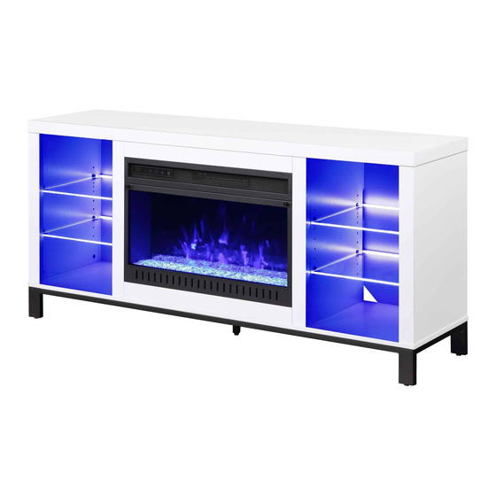
Parkview 60" Fireplace Console
If you have any questions regarding assembly or if parts are missing, DO NOT return this item to the
store where it was purchased. Please call our toll-free customer service number and have your
instructions and parts list ready to provide the model name, part name or factory number:
Or visit our web site 24 hours a day, 7 days a week for product assistance at
THIS INSTRUCTION BOOKLET CONTAINS IMPORTANT SAFETY INFORMATION.
Model # MNFP60PV26WT
# MNFP60PV26BK
ADULT ASSEMBLY REQUIRED
Pacific Standard Time: 8:30 a.m. - 4:30 p.m., Monday - Friday
www.whalenfurniture.com
Or e-mail your request to parts@whalenfurniture.com
PLEASE READ AND KEEP FOR FUTURE REFERENCE.
Date 2021-04-22
1-866-942-5362
Rev. 0001-A
LOT NUMBER:
DATE PURCHASED: /
/
Advertisement

Related Manuals for Whalen MNFP60PV26WT


Summary of Contents for Whalen MNFP60PV26WT
- Page 1 LOT NUMBER: DATE PURCHASED: / Parkview 60” Fireplace Console Model # MNFP60PV26WT # MNFP60PV26BK ADULT ASSEMBLY REQUIRED If you have any questions regarding assembly or if parts are missing, DO NOT return this item to the store where it was purchased. Please call our toll-free customer service number and have your...
- Page 2 IMPORTANT Before you begin: Open, identify and count all parts prior to assembly. Lay out parts on a flat and non-abrasive surface. You will need the parts identified on page 4 and 5 of this instruction manuals. NOTE: IT IS VERY IMPORTANT TO USE GLUE WITH THE DOWELS. EXCESS GLUE CAN BE WIPED OFF WITH A DAMP CLOTH.
-
Page 3: Important Safety Instructions
Carefully Read all Instructions Installing and Operating Fixture IF YOU HAVE ANY QUESTIONS REGARDING THE PROPER INSTALLATION CONSULT A QUALIFIED ELECTRICIAN TO REDUCE THE RISK OF FIRE, ELECTRICAL SHOCK OR INJURY TO PERSONS, PLEASE FOLLOW THE NEXT: Use only insulated staples or plastic ties to secure the cords. ... - Page 4 Parts and Hardware List Please read completely through the instructions and verify that all listed parts and hardware are present before beginning assembly. A- Top Panel (Qty. 1) B- Bottom Panel (Qty. 1) C- Side Panel (Qty. 2) D- Left Partition Panel (Qty. 1) E- Right Partition Panel (Qty.
- Page 5 Parts and Hardware List Please read completely through the instructions and verify that all listed parts and hardware are present before beginning assembly. (1) Cam Lock (2) Cam Bolt (3) M8 x 30 mm Wood Dowel (Qty. 38+1 extra) (Qty. 38+1 extra) (Qty.
- Page 6 Assembly Instructions NOTE: Please do not fully tighten all bolts until you finish assembling all parts. Once assembled, go back and fully tighten all bolts. This will make the assembly easier. 1. Unpack the unit and confirm that you have all the hardware and required parts. Assemble the unit on a carpeted floor or the empty carton to avoid any scratch.
- Page 7 Assembly Instructions The edges are flush with each other 4. Align and attach the Side Panel Moldings (F) to the Side Panels (C) by engaging three Cam Locks (1) in each. (Refer to page 2 on Cam Lock system operation supplement). The edges are flush with each other 5.
- Page 8 Assembly Instructions The edges are flush with each other 6. Repeat the same procedure to attach the other Middle Stile (G) to the Right Partition Panel (E). 7. Attach two Firebox Short Supports (K) to the Firebox Long Support (I) by engaging two cam locks (1).
- Page 9 Assembly Instructions 8. Attach the previous assembly to the Bottom Panel (B) by engaging six Cam Locks (1). 9. Attach the Middle Crossbar (H) to the Top Panel (A) with two Cam Locks (1).
- Page 10 Assembly Instructions The stiles line up with the firebox long support 10. Using the wood dowels as a guide, firmly press the Partition Panels (D and E) to the Bottom Panel (B) and fasten them in place with four 50 mm Screws (8). Fully tighten the screws with a Phillips screwdriver.
- Page 11 Assembly Instructions The crossbar faces upward 12. Place the Top Panel (A) onto the vertical panels properly and fasten it in place by engaging eight Cam Locks (1). 12 11 13. Attach the Base Side Stretchers (O) and Base Middle Stretcher (P) to the Base Back Stretcher (N) by inserting six 16 mm Bolts (11) with Washers (12 and 13) throught the metal tabs and secure them into place.
- Page 12 Assembly Instructions 15. Fasten the assembled base to the Bottom Panel (B) with sixteen 32 mm Screws (6). H/ I 16. Ask for assistance to flip the unit around at its front edges as shown. 17. With the pilot holes as a guide, fasten the Middle Crossbar (H) and Firebox Long Support (I) to the Middle Stiles (G) by attaching four Mending Plates (9) at the joints, using two 12 mm Screws (4) per plate.
- Page 13 Assembly Instructions The cutouts run against the partition panel 18. Now, go back and securely tighten all the cam locks and screws. Make sure that all the parts are tight and there are no gaps between the parts. This will help keep the unit square. 19.
- Page 14 Assembly Instructions 22. Ask for assistance to lift the assembly unit upright and position it near the final location. 23. Insert the Shelf Supports (14) into the holes at the desired height inside each side compartment. Make sure you place four shelf supports in the same level. Tilt and orientate the Glass Shelves (L) onto the Shelf Supports (14) properly and carefully route the USB cable through the slot on the Partition Panels (D and E).
- Page 15 Assembly Instructions 25. Lift the fireplace insert carefully into the back of the assembled mantel and center it on the Firebox Short Supports (K) in the opening. 26. Using the pilot holes as a guide, fasten two L-shaped Metal Brackets (10) onto the Firebox Holder (J) with four 15 mm Pan Head Screws (7).
- Page 16 Assembly Instructions NOTE: To prevent your TV from tipping, you must install the acrylic TV stopper if you place a flat panel television on the top panel. Otherwise, skip to step 30. 29. Remove the paper backing from the Acrylic Stopper (15), then properly align the acrylic stopper into the cut-out on the acrylic stopper template on the Top Panel (A).
- Page 17 Assembly Instructions Wooden stud Wall Short screw Nylon strap Wall Floor leveler Long screw Metal bracket Tools required (not provided): Phillips screwdriver, stud finder, tape measure, pencil, power drill and 1/8” drill bit. 31. Ask for assistance to position the assemble fireplace at the desired location against a wall. If necessary, adjust the pre-attached floor levelers at the bottom of the long stretchers (N) to correct the tilting.
- Page 18 Care and Maintenance Use a soft, clean cloth that will not scratch the surface when dusting. Use of furniture polishes is not necessary. Should you choose to use polishes, test first in an inconspicuous area. Using solvents of any kind on your furniture may damage the finish. ...
-
Page 19: Quality Guarantee
Should this product be defective in workmanship or materials or fail under normal use, we will repair or replace it for up to one (1) year from date of purchase. Every Whalen Furniture product is designed to meet your highest expectations. We guarantee that you will immediately see the value of our fine furniture.
Need help?
Do you have a question about the MNFP60PV26WT and is the answer not in the manual?
Questions and answers