Table of Contents
Advertisement
Quick Links
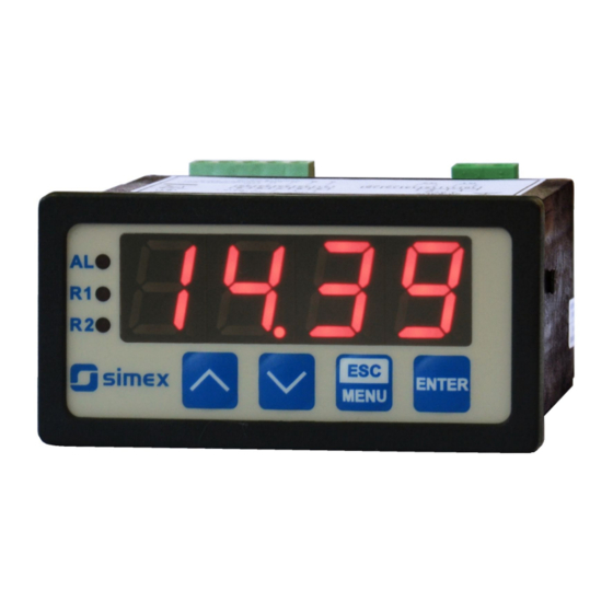
Firmware: v.5.18 or higher
•
Input type: 0-60/75/100/150 mV
•
Two-colour display
•
Read the user's manual carefully before starting to use the unit or software.
Producer reserves the right to implement changes without prior notice.
2018.12.20
User manual
METER
SRP-73-XC
Assisting the automation
industry since 1986
SRP-73-XC_INSSXEN_v.2.09.001
Advertisement
Table of Contents

Related Manuals for Simex SRP-73-XC


Summary of Contents for Simex SRP-73-XC
- Page 1 Assisting the automation industry since 1986 User manual METER SRP-73-XC Firmware: v.5.18 or higher • Input type: 0-60/75/100/150 mV • Two-colour display • Read the user's manual carefully before starting to use the unit or software. Producer reserves the right to implement changes without prior notice.
-
Page 2: Table Of Contents
User manual - METER SRP-73-XC CONTENTS 1. BASIC REQUIREMENTS AND USER SAFETY..................3 2. GENERAL CHARACTERISTICS........................4 3. TECHNICAL DATA............................4 4. DEVICE INSTALLATION..........................6 4.1. UNPACKING............................6 4.2. ASSEMBLY............................6 4.3. CONNECTION METHOD........................8 4.4. MAINTENANCE..........................12 5. FRONT PANEL DESCRIPTION........................13 6. PRINCIPLE OF OPERATION........................13 6.1. MEASUREMENT MODE........................13... -
Page 3: Basic Requirements And User Safety
User manual - METER SRP-73-XC Explanation of symbols used in the manual: - This symbol denotes especially important guidelines concerning the installation and operation of the device. Not complying with the guidelines denoted by this symbol may cause an accident, damage or equipment destruction. -
Page 4: General Characteristics
2. GENERAL CHARACTERISTICS The SRP-73-XC meter is equipped with one voltage input 0-60 / 0-75 / 0-100 / 0-150mV. The selection of active input is realised by software, and selected input can be changed at any time. - Page 5 User manual - METER SRP-73-XC Outputs relay: 0, 1 or 2 NO 1A/250V AC (cos j = 1) or OC-type: 0, 1 or 2; 30mA / 30VDC / 100mW sensor power supply: 24V +5%, -10% / max. 100 mA, stabilized...
-
Page 6: Device Installation
User manual - METER SRP-73-XC 4. DEVICE INSTALLATION The unit has been designed and manufactured in a way assuring a high level of user safety and resistance to interference occurring in a typical industrial environment. In order to take full advantage of these characteristics installation of the unit must be conducted correctly and according to the local regulations. - Page 7 User manual - METER SRP-73-XC 66,5 mm 8 mm 8 mm 8 mm 8 mm max. 5 mm 1 mm 1 mm 68 mm max. 5 mm Figure 4.1. Mounting hole dimensions: a) recommended b) allowable 92 mm 5 mm...
-
Page 8: Connection Method
User manual - METER SRP-73-XC 91 mm Figure 4.3. Minimum distances when assembly of a number of units 4.3. CONNECTION METHOD Caution - Installation should be conducted by qualified personnel . During installation all available safety requirements should be considered. The fitter is responsible for executing the installation according to this manual, local safety and EMC regulations. - Page 9 User manual - METER SRP-73-XC - Unused terminals (marked as n.c.) must not be used for connecting any connecting cables (e.g. as bridges), because this can cause damage to the equipment or electric shock. - If the unit is equipped with housing, covers and sealing to, protecting against water intrusion, pay special attention to their correct tightening or clamping.
- Page 10 User manual - METER SRP-73-XC 6-7 mm 6-7 mm Figure 4.4. Method of cable insulation replacing and cable terminals +24V +5%, -10% RS - 485 Power max = 100mA supply optional) DATA+ (depending on version) DATA- 13 14 18 19 20...
- Page 11 User manual - METER SRP-73-XC 13 14 FUSE FUSE Depending on version: 85...230...260V AC/DC or 19...24...50V DC; 16...24...35V AC Figure 4.7. Connection of power supply and relays Contacts of relay outputs are not equipped with spark suppressors. While use the relay outputs for switching of inductive loads (coils, contactors, power relays, electromagnets, motors etc.) it is required...
-
Page 12: Maintenance
User manual - METER SRP-73-XC Figure 4.8. Examples of suppression circuit connection: a) to relay terminals; b) to the inductive load 16 17 16 17 Logic controller LED 10 mA voltage input 24 V Figure 4.9. Example of OC-type outputs connection 4.4. -
Page 13: Front Panel Description
User manual - METER SRP-73-XC Product marked with this symbol should not be placed in municipal waste. Please check local regulations for disposal of electronic products. 5. FRONT PANEL DESCRIPTION alarm LED indicator (AL) display Thresholds exceeding ENTER LED indicators (R) -
Page 14: Detection Of The Peak Values
Configuration of the device (via menu or RS-485 interface) do not stops measures . 6.2. DETECTION OF THE PEAK VALUES The SRP-73-XC controller is equipped with peaks detection function. It can detect a peaks of the input signal and display their values. Presets connected with this function are placed in ”HOLd”... -
Page 15: Control Of The Relay Outputs
User manual - METER SRP-73-XC measure ”timE” ”timE” ”PEA” ”PEA” time real measurement result display value Figure 6.2. Process of peaks detection 6.3. CONTROL OF THE RELAY OUTPUTS The control of the object (measured signal) is realized via relay outputs. Front panel LEDs named „R”... - Page 16 User manual - METER SRP-73-XC state of relay/LED ”SEtP” parameter zone B zone A measure ”HYSt” parameter Figure 6.3. One threshold control of the relay/LED outputs state of relay/LED ”SEtP” or ”SEt2” parameter zone B zone B zone A measure ”HYSt”...
-
Page 17: One Threshold Mode
User manual - METER SRP-73-XC 6.3.1. One threshold mode Figure 6.5 presents the principle of relay outputs operation for one threshold mode, and an example values of other parameters. measured “SEtP” parameter displayed value signal (expected signal value) zone A “HYSt”... -
Page 18: Two Thresholds Mode
User manual - METER SRP-73-XC (when input signal stay in zone A or zone B) are lower than parameters “t on” If t or t or “toFF”, the relay will not change his state (see points A and C, Figure 6.5 a, d, e). -
Page 19: Device Programming
User manual - METER SRP-73-XC Figure 6.6 presents the principle of relay outputs operation for two thresholds mode, and an example values of other parameters. In this mode parameter “SEt2” is accessible in common with “SEtP” , this parameter describes a second threshold of the relay output. The parameters “HYSt”, “modE”, “t on”, “toFF”, “unit”... -
Page 20: Parameters Edition
User manual - METER SRP-73-XC Functions of the buttons while sub-menu and parameters choice: Selection of sub-menu or parameter for editing. Name of selected item (sub- menu or parameter) is displayed. Operation of [ENTER] button depend on present menu position: ENTER •... -
Page 21: Switch Parameters ("List" Type)
User manual - METER SRP-73-XC Press [ENTER] at least 2 seconds to accept the changes, after that question ”Set?” is displayed, and user must to confirm (or cancel) the changes. To conform changes (and story it in EEPROM) press [ENTER] button shortly after ”SEt?” is displayed. To cancel the changes press [ESC] button shortly after ”SEt?”... -
Page 22: Rel1" Menu
User manual - METER SRP-73-XC 7.3.1. “rEL1” menu This menu allows to configure the operation mode of relays and LEDs marked „ R ” (e.g. „ R1 ”). If there are few relay outputs available, then every output has its own configuration menu (e.g. - Page 23 User manual - METER SRP-73-XC - two threshold mode, relay is turned ON when the input value is bigger “out” than “bigger threshold + HYSt” and lower than “lower threshold – HYSt” , and turned on when the input signal is contained in the second zone.
-
Page 24: Inpt" Menu
User manual - METER SRP-73-XC If parameter „ AL ” = „ on ”, the relay will be turned on in the critical situations, • even if his parameter “modE” = ”noAC”. 7.3.2. “inPt” menu This menu presets the measurement input: “... - Page 25 User manual - METER SRP-73-XC Coordinate „ X ” defines the percentage ratio of input current to selected current range. The „X” range: -99,9 ÷ 199,9. Coordinate „Y” defines displayed value for particular „ X ” value. The „ Y ” value can be changed in range: -999 ÷ 9999, decimal point position depend on „Pnt”...
-
Page 26: Bri" Parameter
User manual - METER SRP-73-XC ”Hi r” = 5,0 % (3 mV) nominal measurement range (4-20mA) [mV] permissible measurement range measurement result is displayed display display regardless on nominal range exceeding message ”-Lo-” message ”-Hi-” Figure 7.1 Example of definition of permissible range of input signal - “Hi r”... -
Page 27: Hold" Menu
User manual - METER SRP-73-XC ”on” - control for selected relay is on, the display will change its colour after selected relay becomes active. “C AL” - control the display colour according to alarm situations : ”oFF” - control is off, ”on”... -
Page 28: Secu" Menu
User manual - METER SRP-73-XC “modE” - the type of detected changes of the input signal, can be set to values: ”norm” peaks, peak and next drop of the input signal of value equal at least “PEA” , ”inv” - drops, drop and next peak of the input signal of value equal at least “PEA”, “PEA”... -
Page 29: Edit" Parameter
User manual - METER SRP-73-XC ”bAud” - this parameter determines RS-485 interface baud rate. It can be set to one of 8 possible values: ”1.2”, ”2.4”, ”4.8”, ”9.6”, ”19.2”, ”38.4”,”57.6”,”115.2”, which respond to the baud rates of 1200, 2400, 4800, 9600, 19200, 38400, 57600 and 115200 bit/s respectively. -
Page 30: Defs" Parameter
User manual - METER SRP-73-XC 7.3.9. ”dEFS” parameter This setting allows to restore the factory settings of the device. To get the access to this option special password is required: „5465”, next the device displays acknowledge question „SEt?” . Press [ENTER] to acknowledge the restoring of factory settings or [ESC] to cancel. -
Page 31: Menu Structure
User manual - METER SRP-73-XC 7.4. MENU STRUCTURE Measurement mode Press and hold at least 2 seconds MENU MENU 4-digit user password entering (if it is different from „0000”) 0 _ _ _ ENTER ENTER ENTER Parameter MENU rEL1 SEtP... - Page 32 User manual - METER SRP-73-XC See previous page ENTER ENTER Parameter MENU SCoL edition ENTER MENU C r1 C r2 C AL MENU ENTER ENTER Parameter MENU modE HOLd edition C Pr ENTER MENU timE Visible only if SEtP „C Pr” = „on”...
-
Page 33: The Alarm Led
User manual - METER SRP-73-XC 8. THE ALARM LED The ALARM LED ( AL ) is turned on when input signal is out of the permissible input range. See parameters: “tyPE” and “Hi r” in paragraph „InPt” menu. 9. DISPLAYED VALUES CALCULATION The first step to compute the result of measure is the calculation of the normalized result (it means result of 0-1 range). -
Page 34: Linear Characteristic
User manual - METER SRP-73-XC 9.1.1. Linear characteristic The normalized result is converted by fixed coefficients determined by “Lo C” and “Hi C” parameters (when the normalized results is equal 0, then value “Lo C” is displayed, and when the normalized results is equal 1, then value “Hi C” is displayed). Expression presented below... -
Page 35: Square Root Characteristic
User manual - METER SRP-73-XC 9.1.3. Square root characteristic The normalized result is rooted and further conversion is done as for linear characteristic. Conversion is made accordingly with the expression: × "Hi C" −"Lo C" "Lo C" , where W means the displayed value. -
Page 36: Examples Of Calculations
User manual - METER SRP-73-XC Normalized measurement U (for 0-100 mV range) 0,35 5-elements characteristic X (PH) = „70.0.” Y (PH) X = „35.0.” Y (PL) X (PL) = „50.0.” X = „20.0.” Prąd wejściowy [mA] X = „90.0.” X = „100.0.”... - Page 37 User manual - METER SRP-73-XC a) U =37.5 mV and U = 0.375 Accordingly to expression on page 34 for linear characteristic: 0,375 × [1200 -(- 300)] @ 562 and next, the “Lo C” value is added to the result , so the...
-
Page 38: The Modbus Protocol Handling
User manual - METER SRP-73-XC Example 6: The user defined characteristic Let the input mode = 0-100 mV, and the user selected the 10 segment characteristic. To do this it is necessary to enter X and Y coordinates of 11 points (see Menu ”inPt”). -
Page 39: List Of Registers
User manual - METER SRP-73-XC The device parameters and display value are available via RS-485 interface, as HOLDING- type registers (numeric values are given in U2 code) of Modbus RTU protocol. The registers (or groups of the registers) can be read by 03h function, and wrote by 06h (single registers) or 10h (group of the registers) accordingly to Modbus RTU specification. - Page 40 User manual - METER SRP-73-XC Register Write Range Register description Parameters of “SECU” menu (binary format (0 - „oFF”, 1 - „on”): see descr. bit 0 - “A r1” parameter; bit 1 - “A r2” parameter bit 2 - “A r3” parameter; bit 3 - “A r4” parameter “rESP”...
-
Page 41: Transmission Errors Description
User manual - METER SRP-73-XC Register Write Range Register description “modE” parameter in “HOLd” menu (type of detected changes): 0 ÷ 1 0 - peaks; 1 - drops “PEA” parameter in “HOLd” menu (minimum detectable change, no 0 ÷ 9999 decimal point included) “timE”... -
Page 42: Examples Of Query/Answer Frames
Data byte count in answer frame DATA H,L Data byte (Hi and Lo byte) CRC L,H CRC error check (Hi and Lo byte) 1. Read of the displayed value (measurement), SRP-73-XC device address = 01h: ADDR FUNC REG H,L COUNT H,L... - Page 43 User manual - METER SRP-73-XC ADDR FUNC REG H,L COUNT H,L CRC L,H The answer: ADDR FUNC BYTE C DATA H,L CRC L,H DATA - identification code (20FFh) 3. Change of the device address from 1 to 2 (write to reg. 20h)
- Page 44 User manual - METER SRP-73-XC The answer: ADDR FUNC BYTE C DATA H1,L1 DATA H2,L2 DATA H3,L3 CRC L,H DATA H1, L1 - reg. 01h (10 - displayed value ”1.0”), DATA H2, L2 - reg. 02h (0 - no errors),, DATA H3, L3 - reg.
-
Page 45: Default And User's Settings List
User manual - METER SRP-73-XC 11. DEFAULT AND USER'S SETTINGS LIST Desc. Parameter Description Default value User's value page Parameters of relay R1 operation (“rEL1” menu) SEtP Relay R1 threshold 20.0 SEt2 Relay R1 second threshold 40.0 HYSt Hysteresis of relay R1... - Page 46 User manual - METER SRP-73-XC Desc. Parameter Description Default value User's value page C AL Change display colour after alarm occurs Enable additional threshold while signalisation via C Pr colour The direction of result changes activating change of morE display colour...
- Page 47 User manual - METER SRP-73-XC...
- Page 48 SIMEX Sp. z o.o. ul. Wielopole 11 80-556 Gdańsk Poland tel.: (+48 58) 762-07-77 fax: (+48 58) 762-07-70 http://www.simex.pl e-mail: info@simex.pl...
Need help?
Do you have a question about the SRP-73-XC and is the answer not in the manual?
Questions and answers