Table of Contents
Advertisement
Quick Links
Advertisement
Table of Contents

Related Manuals for Simex SIMPACT SPI-94


Summary of Contents for Simex SIMPACT SPI-94
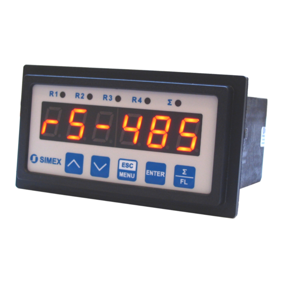
- Page 1 ® SIMEX USER MANUAL for flow meter with pulse input family: SPI-94 type: 1.04 firmware version: or higher Read the user's manual carefully before starting to use the unit. Producer reserves the right to implement changes without prior notice. V.2.00...
-
Page 2: Table Of Contents
User manual for flow meter with pulse input SPI-94 CONTENTS 1. BASIC REQUIREMENTS AND USER SAFETY..................3 2. GENERAL CHARACTERISTICS........................4 3. TECHNICAL DATA............................4. DEVICE INSTALLATION..........................7 4.1. UNPACKING............................4.2. ASSEMBLY............................7 4.3. CONNECTION METHOD........................9 4.4. MAINTENANCE..........................5. FRONT PANEL DESCRIPTION........................15 6. PRINCIPLE OF OPERATION........................15 6.1. -
Page 3: Basic Requirements And User Safety
User manual for flow meter with pulse input SPI-94 Explanation of symbols used in the manual: - This symbol denotes especially important guidelines concerning the installation and operation of the device. Not complying with the guidelines denoted by this symbol may cause an accident, damage or equipment destruction. -
Page 4: General Characteristics
User manual for flow meter with pulse input SPI-94 - Do not use the unit in areas with significant temperature variations, exposed to condensation or icing. - Do not use the unit in areas exposed to direct sunlight. - Make sure that the ambient temperature (e.g. inside the control box) does not exceed the recommended values. -
Page 5: Technical Data
User manual for flow meter with pulse input SPI-94 3. TECHNICAL DATA Power supply voltage 85... 230 ...260V AC/DC; 50 ÷ 60 Hz (depending on version) or 19...24...50V DC; 16...24...35V AC External fuse (required) T - type, max. 2 A Power consumption max. - Page 6 User manual for flow meter with pulse input SPI-94 Housing type panel Housing material NORYL - GFN2S E1 Housing dimensions 96 x 48 x 100 mm Mounting hole 90.5 x 43 mm Assembly depth 102 mm Panel thickness max. 5 mm Operating temperature 0°C to +50°C Storage temperature...
-
Page 7: Device Installation
User manual for flow meter with pulse input SPI-94 4. DEVICE INSTALLATION The unit has been designed and manufactured in a way assuring a high level of user safety and resistance to interference occurring in a typical industrial environment. In order to take full advantage of these characteristics installation of the unit must be conducted correctly and according to the local regulations. - Page 8 User manual for flow meter with pulse input SPI-94 90,5 mm 13 mm 8 mm 8 mm 13 mm max. 5 mm 1 mm 1 mm Figure 4.1. Mounting hole dimensions 92 mm 8 mm 12 mm Figure 4.2. Installing of brackets, and dimensions of connectors. 115 mm Figure 4.3.
-
Page 9: Connection Method
User manual for flow meter with pulse input SPI-94 4.3. CONNECTION METHOD Caution - Installation should be conducted by qualified personnel . During installation all available safety requirements should be considered. The fitter is responsible for executing the installation according to this manual, local safety and EMC regulations. - Page 10 User manual for flow meter with pulse input SPI-94 Due to possible significant interference in industrial installations appropriate measures assuring correct operation of the unit must be applied. To avoid the unit of improper indications keep recommendations listed below. Avoid common (parallel) leading of signal cables and transmission cables together with –...
- Page 11 User manual for flow meter with pulse input SPI-94 (optional) +24V +5%, -10% RS - 485 Power max = 100mA supply DATA+ (depending on version) DATA- 5 6 7 8 9 10 11 12 13 14 15 16 17 18 19 20 n.c.
- Page 12 User manual for flow meter with pulse input SPI-94 10 11 12 13 14 15 FUSE FUSE Depending on version: 85...230...260V AC/DC or 19...24...50V DC; 16...24...35V AC Figure 4.8. Connection of power supply and relays Contacts of relay outputs are not equipped with spark suppressors. While use the relay outputs for switching of inductive loads (coils, contactors, power relays, electromagnets, motors etc.) it is required to use additional...
- Page 13 User manual for flow meter with pulse input SPI-94 Figure 4.9. Examples of suppression circuit connection: a) to relay terminals; b) to the inductive load 5 6 7 8 9 16 17 18 19 20 total flow clearing Figure 4.10. Example of connection between flow counter and flow sensor with contactron output...
-
Page 14: Maintenance
User manual for flow meter with pulse input SPI-94 10 11 10 11 Logic controller LED 10 mA voltage input 24 V Figure 4.11. Example of OC-type outputs connection optional ACTIVE current output Logic controller current input 4-20 mA Figure 4.12. Example of current outputs connection (for device with current output only) 4.4. -
Page 15: Front Panel Description
User manual for flow meter with pulse input SPI-94 5. FRONT PANEL DESCRIPTION Thresholds exceeding LED indicators (R) total flow mode LED indicator ( Σ ) Σ display programming pushbuttons Σ ENTER MENU Symbols and functions of push-buttons: Symbol used in the manual: [ESC/MENU] Functions: MENU •... - Page 16 User manual for flow meter with pulse input SPI-94 ) and “Ftunit” (min., sec. or h), with resolution defined by “F PrEc” (max. 5 digits after (L or m decimal point). Pulses delivered to device's input (Figure 4.10) are recalculated according with procedure showed below: •...
- Page 17 User manual for flow meter with pulse input SPI-94 digits, buttons [^] and [v] enable switching between more and less significant digits. Positions of currently displayed digits are signalized by flashing decimal points (see example below). Example of switchin g between less and more significant digits of total flow result . Let, total counter result be equal 1236789876543.21: –...
-
Page 18: Detection Of The Peak Values
User manual for flow meter with pulse input SPI-94 6.2. DETECTION OF THE PEAK VALUES The SPI-94 flow meter is equipped with peaks detection function. It can detect a peaks of the input signal and display their values. Presets connected with this function are placed in ”HOLd”... - Page 19 User manual for flow meter with pulse input SPI-94 Modes of the control can be changed depend on the values of parameters “vALUE”, “SEt P”, “SEt P2” , “HYSt ” , “modE” , “t on” , “t oFF” , “unit” and “ALArmS” (available in ”rELAy1”...
-
Page 20: One Threshold Mode
User manual for flow meter with pulse input SPI-94 6.3.1. One threshold mode Figure 6.5 presents the principle of relay outputs operation for one threshold mode, and an example values of other parameters. measured “SEt P” parameter displayed value signal (expected signal value) zone A “HYSt”... -
Page 21: Two Thresholds Mode
User manual for flow meter with pulse input SPI-94 (when input signal stay in zone A or zone B) are lower than parameters “t on” If t or t or “t oFF”, the relay will not change his state (see points A and C, Figure 6.5 a, d, e). The state of relay output while the input value exceeds the border values (points A, B, C, D) is described by parameter “modE”. -
Page 22: Device Programming
User manual for flow meter with pulse input SPI-94 Figure 6.6 presents the principle of relay outputs operation for two thresholds mode, and an example values of other parameters. In this mode parameter “SEt P2” is accessible in common with “SEt P2” , this parameter describes a second threshold of the relay output. The parameters “HYSt”, “modE”, “t on”, “t oFF”, “unit”... -
Page 23: Parameters Edition
User manual for flow meter with pulse input SPI-94 Pay attention when device parameters are being changed. If it is possible, turn off controlled installation (machine). Functions of the buttons while sub-menu and parameters choice: Selection of sub-menu or parameter for editing. Name of selected item (sub- menu or parameter) is displayed. -
Page 24: Switch Parameters ("List" Type)
User manual for flow meter with pulse input SPI-94 Press [ENTER] at least 2 seconds to accept the changes, after that question ”Set?” is displayed, and user must to confirm (or cancel) the changes. To conform changes (and story it in EEPROM) press [ENTER] button shortly after ”SEt?”... -
Page 25: Relay1" Menu
User manual for flow meter with pulse input SPI-94 7.3.1. “rELAy1” menu This menu allows to configure the operation mode of relays and LEDs marked „ R ” (e.g. „ R1 ”). If there are few relay outputs available, then every output has its own configuration menu (e.g. menu „rELAy2”... - Page 26 User manual for flow meter with pulse input SPI-94 Parameters ”t PrEc” and ”t unit” are available only if total flow counter is used to control relay output ( “vALUE” = ” tot ”). When current flow rate is used to control relays, the unit and precision of the thresholds and hysteresis are defined by parameters “F unit”...
-
Page 27: Beep" Menu
User manual for flow meter with pulse input SPI-94 If time when the input signal exceeds some border value is shorter than “t on” or “t oFF” time, the relay do not change his state (see paragraph: CONTROL OF THE RELAY OUTPUTS). “unit”... - Page 28 User manual for flow meter with pulse input SPI-94 “FrEq” - maximum permitted frequency of pulses delivered to the input. This parameter is expressed in Hz. And can be set to one of all values showed in Tab.7.1. Minimum permitted duration time of Low and High states are related to every “FrEq”...
-
Page 29: Flouu" Menu
User manual for flow meter with pulse input SPI-94 7.3.4. “FLouu” menu This menu presets the measurement input and allows configuration of current flow rate displaying mode: “F PrEc” - decimal point position (precision of flow rate displaying). It can be set to: “... -
Page 30: Init D" Parameter
User manual for flow meter with pulse input SPI-94 “Clrtot” - this option allows zeroing of total flow counter. After selection of this option ask “CLEAr?” is displayed. If user press [ENTER] total flow counter is cleared, else action is cancelled Zeroing of total flow counter is possible via RS-485 interface too. -
Page 31: Output" Menu
User manual for flow meter with pulse input SPI-94 7.3.8. ”OutPUt” menu This menu contains parameters of current output control. Menu is available if the device is equipped witch current output. Current output can be controlled depend on both present measured value and peak value (if peak detection is enabled). -
Page 32: Bright" Parameter
User manual for flow meter with pulse input SPI-94 controlled due to total flow counter result. It can be set to one of two values: “lit.” - Litres “m 3” - cubical meters Parameters ” t PrEc ” and ” t unit ” are available only if total flow counter is used to control active current output (“vALUE”... -
Page 33: Hold" Menu
User manual for flow meter with pulse input SPI-94 7.3.10. ”HOLd” menu This menu contains parameters connected with peak detection function. See also full description of the peak detection function in paragraph: DETECTION OF THE PEAK VALUES “modE” - the type of detected changes of the input signal, can be set to values: “PEA”... -
Page 34: Rs-485" Menu
User manual for flow meter with pulse input SPI-94 7.3.12. ”rS-485” menu This menu is connected with RS-485 interface, and sets his properties: ”Addr” - this parameter defines the address of the device, accordingly to Modbus protocol. It can be set in range from 0 to 199. If the value 0 is set then device, responds to frames with address 255 (FFh). -
Page 35: Edit T" Parameter
User manual for flow meter with pulse input SPI-94 7.3.13. ”Edit t” paramet er This parameter allows to change the edition mode of numerical parameters: ”dig” - the change to “by digit” mode, ”Slid” - slide change mode. 7.3.14. ”dEFS” parameter This setting allows to restore the factory settings of the device. -
Page 36: Menu Structure
User manual for flow meter with pulse input SPI-94 7.4. MENU STRUCTURE Measurement mode Press and hold at least 2 seconds MENU MENU 4-digit user password entering (if it is different from „0000”) 0 _ _ _ ENTER ENTER ENTER Parameter MENU vALUE... - Page 37 User manual for flow meter with pulse input SPI-94 See previous page ENTER ENTER Parameter MENU vALUE FiLtEr edition ENTER MENU MENU droP ENTER ENTER Parameter MENU OUtPUt OUtmod edition ENTER MENU vALUE OUt LO OUt HI ENTER Parameter MENU briGHt edition ENTER...
-
Page 38: Current Output Value Calculation
User manual for flow meter with pulse input SPI-94 8. CURRENT OUTPUT VALUE CALCULATION Let the current output parameters be: “modE” = “on” , “OUt LO” = 100, “OUt HI” = 200, “Lo r” = 5.0, “Hi r” = 5.0 Parameters “Lo r”... - Page 39 User manual for flow meter with pulse input SPI-94 Register Write Range Register description 0 ÷ 999999 Measurement value (no decimal point) The status of the current measurement. 0 – data valid; 0-FFh 20h – device waits for first pulse; A0h –...
- Page 40 User manual for flow meter with pulse input SPI-94 Register Write Range Register description “t PrEc” parameter in “totAL” (precision of of total flow counter 0 ÷ 3 result displaying): 0 - “ 0”; 1 - “ 0.0”; 2 - “ 0.00”; 3 - “0.000” “E clr”...
- Page 41 User manual for flow meter with pulse input SPI-94 Register Write Range Register description “t on” parameter in “rELAy1” menu, expressed in tenth of seconds 0 ÷ 999 or tenth of minutes depend on “unit” parameter “t oFF” parameter in “rELAy1” menu, expressed in tenth of seconds 0 ÷...
- Page 42 User manual for flow meter with pulse input SPI-94 Register Write Range Register description “t unit” parameter in “rELAy2” menu (the unit of thresholds and 0 ÷ 1 hysteresis while relay is controlled due to total flow counter value): 0 - lit.; 1 - m Parameters or relay R3 operation 0 ÷...
- Page 43 User manual for flow meter with pulse input SPI-94 Register Write Range Register description “ALArmS” parameter in “rELAy4” menu: 0 ÷ 2 0 - no changes; 1 - on; 2 - off 0 ÷ 999999 “SEt P2” parameter in “rELAy4” menu, no decimal point included “vALUE”...
-
Page 44: Transmission Errors Description
User manual for flow meter with pulse input SPI-94 Register Write Range Register description “OUtmod” parameter in “OUtPUt” menu (current output mode) current output disabled; 1 - current output enabled with 0÷20mA 0 ÷ 2 mode; 2 - current output enabled with 4÷20mA mode;... -
Page 45: Examples Of Query/Answer Frames
User manual for flow meter with pulse input SPI-94 9.3. EXAMPLES OF QUERY/ANSWER FRAMES Examples apply for device with address 1. All values are represent hexadecimal. Field description: ADDR Device address on modbus network FUNC Function code REG H,L Starting address (address of first register to read/write, Hi and Lo byte) COUNT H,L No. - Page 46 User manual for flow meter with pulse input SPI-94 3. Change of the device address from 1 to 2 (write to reg. 20h) ADDR FUNC REG H,L DATA H,L CRC L,H DATA H - 0 DATA L - new device address (2) The answer (the same as the message): ADDR FUNC...
-
Page 47: Default And User's Settings List
User manual for flow meter with pulse input SPI-94 10. DEFAULT AND USER'S SETTINGS LIST Desc. Parameter Description Default value User's value page Parameters of relay R1 operation (“rELAy1” menu) vALUE Kind of value controlled relay state SEt P Relay first threshold 20.0 SEt P2 Relay second threshold... - Page 48 User manual for flow meter with pulse input SPI-94 Desc. Parameter Description Default value User's value page SEt P2 Relay second threshold 70.0 HYSt Hysteresis of relay Precision of thresholds and hysteresis displaying t PrEc (while relay is controlled due to total flow counter value) The unit of thresholds and hysteresis displaying t unit...
- Page 49 User manual for flow meter with pulse input SPI-94 Desc. Parameter Description Default value User's value page FrEq Maximum input frequency 300 (Hz) ZEro t Maximum time between two following pulses 1.0 (sec.) mEAS t Width of measurement window 0.5 (sec.) Configuration of current flow display (“FLouu”...
- Page 50 User manual for flow meter with pulse input SPI-94 Desc. Parameter Description Default value User's value page ” briGHt Display brightness „bri 6 Configuration of peaks detection function (“HOLd” menu) ” modE Kind of detected changes „norm Minimum detected change timE Maximum time of peak displaying 0.0 (sec.)
- Page 51 User manual for flow meter with pulse input SPI-94...
- Page 52 SIMEX ® SIMEX Sp. z o.o. , ul. Wielopole 7 PL - 80-556 Gdańsk, Poland tel. : (+48 58) 762-07-77, fax: (+48 58) 762-07-70 http://www.simex.com.pl, e-mail: info@simex.com.pl...
Need help?
Do you have a question about the SIMPACT SPI-94 and is the answer not in the manual?
Questions and answers