Table of Contents
Advertisement
Quick Links
Firmware: v.1.04 or higher
•
Input type: universal
•
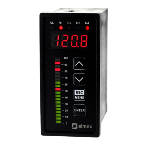
Multicolour bargraph
•
Read the user's manual carefully before starting to use the unit or software.
Producer reserves the right to implement changes without prior notice.
2021.11.05
User manual
METER
SUR-49B
Assisting the automation
industry since 1986
SUR-49B_INSSXEN_v.1.00.002
Advertisement
Table of Contents

Related Manuals for Simex SUR-49B


Summary of Contents for Simex SUR-49B
- Page 1 Assisting the automation industry since 1986 User manual METER SUR-49B Firmware: v.1.04 or higher • Input type: universal • Multicolour bargraph • Read the user's manual carefully before starting to use the unit or software. Producer reserves the right to implement changes without prior notice.
-
Page 2: Table Of Contents
User manual - METER SUR-49B CONTENTS 1. BASIC REQUIREMENTS AND USER SAFETY..................3 2. GENERAL CHARACTERISTICS.......................4 3. TECHNICAL DATA............................5 4. DEVICE INSTALLATION...........................8 4.1. UNPACKING.............................8 4.2. ASSEMBLY............................8 4.3. CONNECTION METHOD........................11 4.4. MAINTENANCE..........................20 5. FRONT PANEL DESCRIPTION.......................20 6. PRINCIPLE OF OPERATION........................21 6.1. MEASUREMENT MODE.........................21... -
Page 3: Basic Requirements And User Safety
User manual - METER SUR-49B Explanation of symbols used in the manual: - This symbol denotes especially important guidelines concerning the installation and operation of the device. Not complying with the guidelines denoted by this symbol may cause an accident, damage or equipment destruction. -
Page 4: General Characteristics
49B with two relays (or OC type) outputs can be equipped with active current output, passive isolated current output or active voltage output. Device SUR-49B is equipped with RS-485 / Modbus RTU communication interface and sensor supply output. The meter can be ordered in two power supply versions. -
Page 5: Technical Data
User manual - METER SUR-49B 3. TECHNICAL DATA Power supply voltage 85...230...260V AC/DC; 50 ÷ 60 Hz (separated) (depending on version) or 19...24...50V DC and 16...24...35V AC (separated) or 11.4...12...15V AC/DC (separated) External fuse (required) T - type, max. 2 A Power consumption max. - Page 6 User manual - METER SUR-49B Thermocouple input K, S, J, T, N, R, B, E Thermocouple input range K: -200˚C ÷ +1370˚C S: -50˚C ÷ +1768˚C J: -210˚C ÷ +1200˚C T: -200˚C ÷ + 400˚C N: -200˚C ÷ +1300˚C R: -50˚C ÷ +1768˚C B: +250˚C ÷...
- Page 7 User manual - METER SUR-49B Communication interface RS-485, 8N1 and 8N2, Modbus RTU, not separated Baud rate 1200 bit/s ÷ 115200 bit/s Displays LED, 9 mm height, red or green, (depending on version) 20-points bargraph, red-green Display range -999 ÷ 9999 plus decimal point...
-
Page 8: Device Installation
User manual - METER SUR-49B 4. DEVICE INSTALLATION The unit has been designed and manufactured in a way assuring a high level of user safety and resistance to interference occurring in a typical industrial environment. In order to take full advantage of these characteristics installation of the unit must be conducted correctly and according to the local regulations. - Page 9 User manual - METER SUR-49B 43 mm 8 mm 13 mm 13 mm 8 mm max. 5 mm 43 mm max. 5 mm Figure 4.1. Mounting hole dimensions: a) recommended b) allowable...
- Page 10 User manual - METER SUR-49B 92 mm 5 mm 12 mm 10 mm Figure 4.2. Installing of brackets, and dimensions of connectors. 67 mm Figure 4.3. Minimum distances when assembly of a number of units.
-
Page 11: Connection Method
User manual - METER SUR-49B 4.3. CONNECTION METHOD Caution - Installation should be conducted by qualified personnel. During installation all available safety requirements should be considered. The fitter is responsible for executing the installation according to this manual, local safety and EMC regulations. - Page 12 User manual - METER SUR-49B Due to possible significant interference in industrial installations appropriate measures assuring correct operation of the unit must be applied. To avoid the unit of improper indications keep recommendations listed below. – Avoid running signal cables and transmission cables together with power supply cables and cables controlling inductive loads (e.g.
- Page 13 User manual - METER SUR-49B RS - 485 Power +24V +5%, -10% supply max = 100mA / 50mA DATA+ DATA- (depending on version) n.c. n.c. 5 6 7 8 9 10 11 12 13 14 15 31 32 33 34 35 n.c.
- Page 14 User manual - METER SUR-49B RS - 485 Power +24V +5%, -10% supply max = 100mA / 50mA DATA+ DATA- (depending on version) n.c. n.c. 5 6 7 8 9 10 11 12 13 14 15 31 32 33 34 35...
- Page 15 User manual - METER SUR-49B RS - 485 Power +24V +5%, -10% Passive, isolated Current output supply max = 100mA / 50mA DATA+ 4÷20mA (optional) DATA- (depending on version) 5 6 7 8 9 10 11 12 13 14 15...
- Page 16 User manual - METER SUR-49B internally connected 24V DC 31 32 33 34 35 31 32 33 34 35 Figure 4.13. Connection of 3-wire current transducer internally connected 24V DC 31 32 33 34 35 31 32 33 34 35 Figure 4.14.
- Page 17 User manual - METER SUR-49B 31 32 33 34 31 32 33 34 31 32 33 34 n.c. n.c. n.c. Ra, Rb, Rc, Rd can be different Ra, Rc can be different Ra = Rc = Rd Figure 4.15. Connection of RTD sensors: a) 4-wires circuit;...
- Page 18 User manual - METER SUR-49B 10 11 10 11 Figure 4.17. Examples of suppression circuit connection: a) to relay terminals; b) to the inductive load 12 13 12 13 LED 10 mA Logic controller voltage input 24 V Figure 4.18. Example of OC-type outputs connection...
- Page 19 User manual - METER SUR-49B ACTIVE current output Logic controller current input 0-20 mA Figure 4.19. Example of active current outputs connection (for device with active current output only) PASSIVE current output Logic controller Isolation loss current input 4-20 mA Figure 4.20.
-
Page 20: Maintenance
User manual - METER SUR-49B 4.4. MAINTENANCE The unit does not have any internal replaceable or adjustable components available to the user. Pay attention to the ambient temperature in the room where the unit is operating. Excessively high temperatures cause faster ageing of the internal components and shorten the fault-free time of the unit's operation. -
Page 21: Principle Of Operation
User manual - METER SUR-49B Symbol used in the manual: [^] [v] Functions : • Change of the present menu, • Modification of the parameter value, • Change of the display mode. 6. PRINCIPLE OF OPERATION After turning the power supply on, device ID and software version are showed on the display, next the controller goes to the measurement mode. -
Page 22: Detection Of The Peak Values
6.1.1. Detection OF THE PEAK VALUES The SUR-49B meter is equipped with peaks detection function. It can detect a peaks of the input signal and display their values. Presets connected with this function are placed in ”HOLd”... - Page 23 User manual - METER SUR-49B holding peak value until [ESC] button is pressed. If „HdiS”=”rEAL” then value "timE"=0.0 means no holding. Displaying peak value is signalized by flashing most right decimal point. The relays/LEDs and analogue outputs can be controlled depend on the current value of input signal or the peak value (see ”HOLd”...
-
Page 24: Control Of The Relay Outputs
User manual - METER SUR-49B 6.2. CONTROL OF THE RELAY OUTPUTS The control of the object (measured signal) is realized via relay outputs. Front panel LEDs named “R” indicates the state of particular relay output. If device is not equipped with one or more relay outputs, menus referring to this relays are available, but apply to LED indicators only. -
Page 25: One Threshold Mode
User manual - METER SUR-49B 6.2.1. One threshold mode 6.7 presents the principle of relay outputs operation for one threshold mode for an example values of other parameters. measured “SEtP” parameter displayed value signal (expected signal value) zone A “HYSt” parameter... -
Page 26: Two Thresholds Mode
User manual - METER SUR-49B turned off (“modE” = ”oFF”) when input signal value is contained in zone A (6.7a). The parameter “AL” allow user to set the relay output behaviour in critical situations (e. g. input values exceeds permissible measurement range). User can select that the relays will be turned on, turned off,or not changed in critical situations. -
Page 27: Device Programming
User manual - METER SUR-49B 6.8 presents the principle of relay outputs operation for two thresholds mode for an example values of other parameters. In this mode parameter “SEt2” is accessible in common with “SEtP”, this parameter describes a second threshold of the relay output. The parameters “HYSt”, “modE”, “t on”, “toFF”, “unit”... -
Page 28: Parameters Edition
User manual - METER SUR-49B Functions of the buttons while sub-menu and parameters choice: Selection of sub-menu or parameter for editing. Name of selected item (sub- menu or parameter) is displayed. Operation of [ENTER] button depend on present menu position: ENTER •... -
Page 29: Switch Parameters ("List" Type)
User manual - METER SUR-49B Press [ENTER] at least 2 seconds to accept the changes, after that question “Set?” is displayed, and user must to confirm (or cancel) the changes. To confirm changes (and story it in EEPROM) press [ENTER] button shortly after “SEt?” is displayed. To cancel the changes press [ESC] button shortly after “SEt?”... -
Page 30: Rel1" Menu
User manual - METER SUR-49B 7.3.1. “ rEL1 ” menu This menu allows to configure the operation mode of relays and LEDs marked „R” (e.g. „R1”). If there are few relay outputs available, then every output has its own configuration menu (e.g. - Page 31 User manual - METER SUR-49B than “bigger threshold + HYSt” and lower than “lower threshold – HYSt”, and turned on when the input signal is contained in the second zone. The bigger threshold means bigger one of “SEtP” and “SEt2”...
-
Page 32: Beep" Menu
User manual - METER SUR-49B • If option “noCH” is selected for “AL” parameter, behaviour of the relay may depend on “FiLt” parameter in some cases. If “FiLt” is set to big value and the input signal drops, result value of the measure will change slow, causes of turning on or off relay due to thresholds values. -
Page 33: Inpt" Menu (Parameters Of Temperature Inputs)
User manual - METER SUR-49B For current and voltage inputs displayed values are defined by parameters “Lo C”,”Hi C” (or by user defined characteristic points) and parameter ”Pnt”. ”FiLt” - option allows to change the filtration time constant. Expressed in seconds. - Page 34 User manual - METER SUR-49B If user defined characteristic is selected (parameter “CHAr” = ”USEr”) the parameters „Lo C” and „Hi C” are not available for modification, due to their values are calculated from defined characteristic. “AddP” - this menu allow user to add single point to the user defined characteristic.
-
Page 35: Outp" Menu
User manual - METER SUR-49B ”Lo r” = 75,0% (3 mA) ”Hi r” = 5,0 % (1 mA) nominal measurement range (4-20mA) [mA] permissible measurement range measurement result is displayed display display regardless on nominal range exceeding message ”-Lo-” message ”-Hi-”... - Page 36 User manual - METER SUR-49B For passive current output: ”oFF” - current output disabled, “4-20” - current output enabled with 4 ÷ 20 mA mode, ”modb” - current output controlled via RS-485 interface. For active voltage output: ”oFF” - voltage output disabled, ”0-5”...
-
Page 37: Bar" Menu
User manual - METER SUR-49B In example on page 49 of the DISPLAY VALUES CALCULATION paragraph the procedure of the analogue outputs determining is presented in details. “AL” - this parameter determines the behaviour of analogue output if any critical situation occurs. -
Page 38: Bri" Parameter
User manual - METER SUR-49B „rEd” black green „g r” green orange „r g” green orange „b g” black green „b r” black green Tab. 7.1. Possible combinations of the bargraph colours “Pr1P” ÷ “Pr4P” - these parameters allows to define which one of the thresholds of the relay will be showed on bargraph. -
Page 39: Hold" Menu
User manual - METER SUR-49B set to conventional values from 1 to 8. 7.3.9. ”HOLd” menu This menu contains parameters connected with peak detection function. See also full description of the peak detection function in paragraph: DETECTION OF THE PEAK VALUES. -
Page 40: Rs" Menu
User manual - METER SUR-49B “A r1 ÷ A r4” - this option permits user (”on”) or prohibits (”oFF”) to modify the thresholds of the relays/LEDs R1 ÷ R4 without knowledge about user password 7.3.11. ”rS” menu This menu is connected with RS-485 interface, and sets his properties. -
Page 41: Edit" Parameter
User manual - METER SUR-49B ”rESP” parameter “ 10c” “ 20c” “ 50c” Tab.7.2. Settings of ”rESP” parameter 7.3.12. ”Edit” paramet er This parameter allows to change the edition mode of numerical parameters. ”dig” - “by digit” change mode, ”Slid”... -
Page 42: Menu Structure
User manual - METER SUR-49B 7.4. MENU STRUCTURE Measurement mode Press and hold at least 2 seconds MENU MENU 0 _ _ _ 4-digit user password entering (if it is different from „0000”) ENTER MENU rEL1 ENTER ENTER Parameter SEtP... - Page 43 User manual - METER SUR-49B See previous page ENTER ENTER Parameter MENU tYPE edition ENTER MENU FCoL ENTER Parameter MENU Lo C edition ENTER MENU Hi C MENU ENTER ENTER Pr1P Parameter MENU modE HOLd edition ENTER MENU Pr2P Pr3P...
-
Page 44: The Alarm Led
User manual - METER SUR-49B 8. THE ALARM LED Alarm LED (AL) lights in cases: • exceeding of permissible measurement range • detection of sensor malfunction (shortcut or break of measurement circuit) 9. OVER-CURRENT PROTECTION The current input of the device is equipped with over-current protection circuit. This circuit protects the standard resistor to damage. -
Page 45: Linear Characteristic
User manual - METER SUR-49B 10.1.1. Linear characteristic The normalized result is converted by fixed coefficients determined by “Lo C” and “Hi C” parameters (when the normalized results is equal 0, then value “Lo C” is displayed, and when the normalized results is equal 1, then value “Hi C” is displayed). Expression presented below... -
Page 46: Square Root Characteristic
User manual - METER SUR-49B 10.1.3. Square root characteristic The normalized result is rooted and further conversion is done as for linear characteristic. Conversion is made accordingly with the expression: × "Hi C"−"Lo C" "Lo C" , where W means the displayed value. -
Page 47: Examples Of Calculations
User manual - METER SUR-49B Normalized measurement I (for 0-20 mA range) 0,35 5-elements characteristic X (PH) = „70.0.” Y (PH) X = „35.0.” Y (PL) X (PL) = „50.0.” X = „20.0.” Prąd wejściowy [mA] X = „90.0.” X = „100.0.”... - Page 48 User manual - METER SUR-49B a) I =10 mA and I = 0,375 Accordingly to expression on page 45 for linear characteristic: 0,375 × [1200 -(- 300)] @ 562 and next, the “Lo C” value is added to the result , so the...
- Page 49 User manual - METER SUR-49B Example 6: The user defined characteristic Let the input mode = 4-20 mA, and the user selected the 10 segment characteristic. To do this it is necessary to enter X and Y coordinates of 11 points (see Menu ”inPt”).
- Page 50 User manual - METER SUR-49B = (17.5-10.0) / (20.0-10.0) × 16 mA + 4 mA = 0.75 ·16 + 4 = 16 mA Calculated I do not exceeds the output working range (3.8 - 21 mA). b) D = „20.5”...
-
Page 51: The Modbus Protocol Handling
User manual - METER SUR-49B 11. THE MODBUS PRO TOCOL HANDLING Transmission parameters: 1 start bit, 8 data bits, 1 or 2 stop bit (2 bits are send, 1 and 2 bits are accepted when receive), no parity control Baud rate:... - Page 52 User manual - METER SUR-49B Register Write Range Register description “Pnt ”parameter in “InPt” menu (the copy of 03h register, decimal 0 ÷ 3 point position): 0 - “ 0”; 1 - “ 0.0”; 2 - “ 0.00”; 3 - “0.000”...
- Page 53 User manual - METER SUR-49B Register Write Range Register description “t on” parameter in “rEL1” menu, expressed in tenth of seconds or 0 ÷ 999 tenth of minutes depend on “unit” parameter - register no. 35h) “toFF” parameter in “rEL1” menu, expressed in tenth of seconds 0 ÷...
- Page 54 User manual - METER SUR-49B Register Write Range Register description “toFF” parameter in “rEL4” menu, expressed in tenth of seconds 0 ÷ 999 or tenth of minutes depend on “unit” parameter - register no. 4Dh) “unit” parameter in “rEL4” menu: 0 ÷...
-
Page 55: Transmission Errors Description
User manual - METER SUR-49B Register Write Range Register description “AL” parameter in “OUtP” menu (current output value on critical 0 ÷ 3 exception): 0 - no change; 1 - 22.1 mA; 2 - 3.4 mA; 3 - 0 mA Parameter“tyPE”... -
Page 56: Examples Of Query/Answer Frames
Data byte count in answer frame DATA H,L Data byte (Hi and Lo byte) CRC L,H CRC error check (Hi and Lo byte) 1. Read of the displayed value (measurement), SUR-49B device address = 01h: ADDR FUNC REG H,L COUNT H,L... - Page 57 User manual - METER SUR-49B ADDR FUNC REG H,L COUNT H,L CRC L,H The answer: ADDR FUNC BYTE C DATA H,L CRC L,H DATA - identification code (23DEh) 3. Change of the device address from 1 to 2 (write to reg. 20h)
- Page 58 User manual - METER SUR-49B ADDR FUNC BYTE C DATA H1,L1 DATA H2,L2 DATA H3,L3 CRC L,H DATA H1, L1 - reg. 01h (10 - displayed value ”1.0”), DATA H2, L2 - reg. 02h (0 - no errors), DATA H3, L3 - reg.
-
Page 59: Default And User's Settings List
User manual - METER SUR-49B 12. DEFAULT AND USER'S SETTINGS LIST Desc. Parameter Description Default value User's value page Parameters of relay R1 operation (“rEL1” menu) SEtP Relay R1 threshold 20.0 SEt2 Relay R1 second threshold 40.0 HYSt Hysteresis of relay R1... - Page 60 User manual - METER SUR-49B Desc. Parameter Description Default value User's value page t on Turn on delay of relay R4 toFF Turn off delay of relay R4 unit Unit of “t on”, “toFF” parameters of relay R4 Reaction for critical situation of relay R4 Activation of acoustic signal (menu “bEEP”)
- Page 61 User manual - METER SUR-49B Desc. Parameter Description Default value User's value page Hi r Extension of the top of the nominal output range 5.0 (%) Current output value on critical exception 22.1 (mA) Active voltage output configuration (“OUtP” menu)
- Page 62 User manual - METER SUR-49B Desc. Parameter Description Default value User's value page H r4 Source of relay R4, and LED R4 control rEAL HOUt Source of current output control rEAL Settings of access to the configuration parameters (“SECu” menu)
- Page 63 User manual - METER SUR-49B...
- Page 64 SIMEX Sp. z o.o. ul. Wielopole 11 80-556 Gdańsk Poland tel.: (+48 58) 762-07-77 fax: (+48 58) 762-07-70 www.simex.pl e-mail: info@simex.pl...
Need help?
Do you have a question about the SUR-49B and is the answer not in the manual?
Questions and answers