Table of Contents
Advertisement
Quick Links
Firmware: v.6.00 or higher
•
Input type: pulse
•
Rotational / linear speed control
•
Read the user's manual carefully before starting to use the unit or software.
Producer reserves the right to implement changes without prior notice.
2018.12.18
User manual
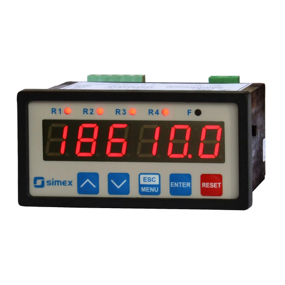
RATEMETER
STI-94
Assisting the automation
industry since 1986
STI-94_INSSXEN_v.2.09.001
Advertisement
Table of Contents

Related Manuals for Simex STI-94


Summary of Contents for Simex STI-94
- Page 1 Assisting the automation industry since 1986 User manual RATEMETER STI-94 Firmware: v.6.00 or higher • Input type: pulse • Rotational / linear speed control • Read the user's manual carefully before starting to use the unit or software. Producer reserves the right to implement changes without prior notice.
-
Page 2: Table Of Contents
User manual - RATEMETER STI-94 CONTENTS 1. BASIC REQUIREMENTS AND USER SAFETY..................3 2. GENERAL CHARACTERISTICS........................4 3. TECHNICAL DATA............................5 4. DEVICE INSTALLATION..........................7 4.1. UNPACKING............................7 4.2. ASSEMBLY............................7 4.3. CONNECTION METHOD........................9 4.4. MAINTENANCE..........................17 5. FRONT PANEL DESCRIPTION........................18 6. PRINCIPLE OF OPERATION........................19 6.1. MEASUREMENT MODE........................19... -
Page 3: Basic Requirements And User Safety
User manual - RATEMETER STI-94 Explanation of symbols used in the manual: - This symbol denotes especially important guidelines concerning the installation and operation of the device. Not complying with the guidelines denoted by this symbol may cause an accident, damage or equipment destruction. -
Page 4: General Characteristics
(or OC type) outputs can be equipped with active current output, passive isolated current output or active voltage output. Device STI-94 is equipped with RS-485 / Modbus RTU communication interface and sensor supply output. The meter can be ordered in two power supply versions. -
Page 5: Technical Data
User manual - RATEMETER STI-94 3. TECHNICAL DATA Power supply voltage 85... 230 ...260V AC/DC; 50 ÷ 60 Hz (separated) (depending on version) or 19...24...50V DC and 16...24...35V AC (separated) External fuse (required) T - type, max. 2 A Power consumption max. - Page 6 User manual - RATEMETER STI-94 range max. 0 ÷ 11V Active voltage output (optional, for two relays or two OC-type output version only) Load resistance min. 2000 W Display range 0.00000 ÷ 999999 Communication interface RS 485, 8N1 and 8N2, Modbus RTU,...
-
Page 7: Device Installation
User manual - RATEMETER STI-94 4. DEVICE INSTALLATION The unit has been designed and manufactured in a way assuring a high level of user safety and resistance to interference occurring in a typical industrial environment. In order to take full advantage of these characteristics installation of the unit must be conducted correctly and according to the local regulations. - Page 8 User manual - RATEMETER STI-94 90,5 mm 13 mm 8 mm 8 mm 13 mm max. 5 mm 1 mm 1 mm Figure 4.1. Recommended mounting hole dimensions 92 mm max. 5 mm Figure 4.2. Allowable mounting hole dimensions 92 mm...
-
Page 9: Connection Method
User manual - RATEMETER STI-94 115 mm Figure 4.4. Minimum distances when assembly of a number of units 4.3. CONNECTION METHOD Caution - Installation should be conducted by qualified personnel . During installation all available safety requirements should be considered. The fitter is responsible for executing the installation according to this manual, local safety and EMC regulations. - Page 10 User manual - RATEMETER STI-94 - If the unit is equipped with housing, covers and sealing packing, protecting against water intrusion, pay special attention to their correct tightening or clamping. In the case of any doubt consider using additional preventive measures (covers, roofing, seals, etc.).
- Page 11 User manual - RATEMETER STI-94 All connections must be made while power supply is disconnected ! Double numeration means, that depending on device version, particular terminal can be marked according to the top or bottom number. Power RS - 485...
- Page 12 User manual - RATEMETER STI-94 Power RS - 485 ACTIVE +24V +5%, -10% supply current output max = 100mA DATA+ (optional) DATA- (depending on version) 5 6 7 8 9 10 11 12 13 14 15 31 32 33 34 35 n.c.
- Page 13 User manual - RATEMETER STI-94 RS - 485 Power ACTIVE +24V +5%, -10% supply current output max = 100mA DATA+ (optional) DATA- (depending on version) 5 6 7 8 9 10 11 12 13 14 15 31 32 33 34 35 n.c.
- Page 14 User manual - RATEMETER STI-94 10 11 12 13 14 15 FUSE FUSE Depending on version: 85...230...260V AC/DC or 19...24...50V DC; 16...24...35V AC Figure 4.14. Connection of power supply and relays Contacts of relay outputs are not equipped with spark suppressors. While use the relay outputs for switching of inductive loads (coils, contactors, power relays, electromagnets, motors etc.) it is required...
- Page 15 User manual - RATEMETER STI-94 Figure 4.15. Examples of suppression circuit connection: a) to relay terminals; b) to the inductive load Construction of pulse input allows connecting of inductive or optical sensor with common earth (Figure 4.16a) or common plus (Figure 4.16b), without additional intermediary circuits (sensor with NPN or PNP type output).
- Page 16 User manual - RATEMETER STI-94 10 11 10 11 Logic controller LED 10 mA voltage input 24 V Figure 4.17. Example of OC-type outputs connection ACTIVE current output Logic controller current input 0-20 mA Figure 4.18. Example of active current outputs connection...
-
Page 17: Maintenance
User manual - RATEMETER STI-94 ACTIVE voltage output Logic controller voltage input 0 - 10V Figure 4.20. Example of active voltage outputs connection (for device with active voltage output only) 4.4. MAINTENANCE The unit does not have any internal replaceable or adjustable components available to the user. -
Page 18: Front Panel Description
User manual - RATEMETER STI-94 5. FRONT PANEL DESCRIPTION Thresholds exceeding LED indicators (R) alarm LED indicator (F) display programming pushbuttons ENTER RESET MENU Symbols and functions of push-buttons: Symbol used in the manual: [ESC/MENU] Functions: MENU • Enter to main menu ( press and hold by at least 2 sec.) •... -
Page 19: Principle Of Operation
User manual - RATEMETER STI-94 6. PRINCIPLE OF OPERATION After turning the power supply on, device ID and software version are showed on the display, next the controller goes to the measurement mode. 6.1. MEASUREMENT MODE In the measurement mode the device shows current measurement value (rotational revolution, it depends on “F or P”... -
Page 20: Detection Of The Peak Values
6.2. DETECTION OF THE PEAK VALUES The STI-94 controller is equipped with peaks detection function. It can detect a peaks of the input signal and display their values. Presets connected with this function are placed in “HOLd” menu (see description of “HOLd” menu). The detection of the peak can be done if the measured signal raises and drops of value at least equal to parameter “PEA”. -
Page 21: Control Of The Relay Outputs
User manual - RATEMETER STI-94 6.3. CONTROL OF THE RELAY OUTPUTS The control of the object (measured signal) is realized via relay outputs. Front panel LEDs named „ R ” indicates the state of particular relay output. If device is not equipped with one or more relay outputs, menus refer to this relays are available, but apply to LED indicators only. -
Page 22: One Threshold Mode
User manual - RATEMETER STI-94 6.3.1. One threshold mode Figure 6.4 presents the principle of relay outputs operation for one threshold mode, and an example values of other parameters. measured “SEt P” parameter displayed value signal (expected signal value) zone A “HYSt”... -
Page 23: Two Thresholds Mode
User manual - RATEMETER STI-94 (when input signal stay in zone A or zone B) are lower than parameters “t on” If t or t or “t oFF”, the relay will not change his state (see points A and C, Figure 6.4 a, d, e). -
Page 24: Device Programming
User manual - RATEMETER STI-94 Figure 6.5 presents the principle of relay outputs operation for two thresholds mode, and an example values of other parameters. In this mode parameter “SEt P2” is accessible in common with “SEt P2” , this parameter describes a second threshold of the relay output. The parameters “HYSt”, “modE”, “t on”, “t oFF”, “unit”... -
Page 25: Parameters Edition
User manual - RATEMETER STI-94 Functions of the buttons while sub-menu and parameters choice: Selection of sub-menu or parameter for editing. Name of selected item (sub- menu or parameter) is displayed. Operation of [ENTER] button depend on present menu position: ENTER •... -
Page 26: Switch Parameters ("List" Type)
User manual - RATEMETER STI-94 7.2.3. Switch parameters (“LIST” type) Switch parameters can be described as a sets of values (a lists) out of which only one of the options available on the list can be selected for the given parameter. Options of switching parameter are selected using keys. - Page 27 User manual - RATEMETER STI-94 • The relay outputs and LEDs (named “R“) can be controlled depend on both - the current value and the peak value (when peak detection is active) of the input signal. • If device is not equipped with one or more relay outputs, menus refer to this relays are available, but apply to LED indicators only.
-
Page 28: Beep" Menu
User manual - RATEMETER STI-94 LEDs light when relays are closed, independently of relays' mode. • • When power supply fail, unit do not store relays state selected by RS-485 interface. “t on” - turn on delay time, the relay is turned on with delay equal “t on” if the input value exceeds appropriate border value (defined with threshold and hysteresis), at least “t on”... -
Page 29: Input" Menu
User manual - RATEMETER STI-94 7.3.3. “ inPUt ” menu This menu contains options of pulse input configuration: “FrEq” - maximum permitted frequency of pulses delivered to the input. This parameter is expressed in Hz. And can be set to one of all values showed in Tab.7.1. - Page 30 User manual - RATEMETER STI-94 “PrEc” - precision of result displaying. There are available settings from “0” (precision of 1 unit) to “0.00000” (precision with 5 digits after decimal point) “unit” - The unit of rotational speed used for recalculation of current measurement can be set to: “SEC”...
-
Page 31: Filter" Menu
User manual - RATEMETER STI-94 7.3.4. “ FiLtEr ” menu This menu contains parameters referred to additional data (result) filtration. “vALUE” - this parameter sets filtration rate. It can be set to values from 0 (no filtration ) to 5 (strongest filtration – time window about 3.5 sec.). - Page 32 User manual - RATEMETER STI-94 W −" OUtL" × B− A A Out= "OUtH" −"OUtL" where: W – displayed value, Out – analogue output value, B – higher range limit (20mA / 5V / 10V), A – lower range limit (0mA / 4mA / 0V / 1V / 2v), “OutL”...
-
Page 33: Bright" Parameter
User manual - RATEMETER STI-94 When the critical situation goes, the output signal will be set to value calculated due to formulas given above. If parameter “OUtmod” is set to “oFF” , “4-20” , “0-20” , “0-5” , “1-5” , “0-10” or “2-10”... -
Page 34: Secu" Menu
User manual - RATEMETER STI-94 7.3.8. ”SECU” menu This menu contains presets connected with availability of other parameters: “SEtcod” - user password (4-digits number). If this parameter is set at value “0000” , user password is turned off. If the user do not remember his password, the access to the menu is possible by the “one-use password”. -
Page 35: Edit T" Parameter
User manual - RATEMETER STI-94 “rESP” - this parameter defines minimal (additional) delay between the Modbus message and the answer of the device (received and sent via RS-485 interface). This additional delay allows the device to work with poor RS-converters which do not works properly on baud rates higher than 19200. -
Page 36: Menu Structure
User manual - RATEMETER STI-94 7.4. MENU STRUCTURE Measurement mode Press and hold at least 2 seconds MENU MENU 4-digit user password entering (if it is different from „0000”) 0 _ _ _ ENTER ENTER ENTER Parameter MENU rELAy1 SEt P... - Page 37 User manual - RATEMETER STI-94 See previous page ENTER ENTER Parameter MENU HOLd modE edition ENTER MENU timE H dis MENU H r1 H r2 H r3 H r4 HOUt ENTER ENTER Parameter MENU SECU SEtcod edition ENTER MENU Acc r1...
-
Page 38: The Alarm Led
User manual - RATEMETER STI-94 8. THE ALARM LED The ALARM LED ( AL ) is turned on when input signal is out of the permissible frequency range. 9. EXAMPLES OF “MUL” AND “DIV ” PARAMETERS CALCULATION 1. Let's assume that user wants to multiply rotational speed by 12.34. Then parameters “mUL”... -
Page 39: Output Value Calculation
User manual - RATEMETER STI-94 10. OUTPUT VALUE CALCULATION Lets assume that we have active current output and its parameters are: “OUtmod” = “4-20” , “OUt LO” = 100, “OUt HI” = 200, “Lo r” = 5.0, “Hi r” = 5.0 Parameters “Lo r”... -
Page 40: List Of Registers
User manual - RATEMETER STI-94 11.1. LIST OF REGISTERS Some parameters are located on two registers (higher word in first register, and lower word in next one). After writing of one of them device controls result of their 32-bit value, and if it is necessary corrects value of second register automatically. - Page 41 User manual - RATEMETER STI-94 Register Write Range Register description “div” parameter in “inPUt” menu 0 ÷ 999999 Value 0 is interpreted as 1 000 000 0 ÷ 399 “ZEro t” parameter in “inPUt” menu expressed in tenth of seconds “mEAS t”...
- Page 42 User manual - RATEMETER STI-94 Register Write Range Register description “t on” parameter in “rELAy1” menu, expressed in tenth of seconds 0 ÷ 999 or tenth of minutes depend on “unit” parameter “t oFF” parameter in “rELAy1” menu, expressed in tenth of 0 ÷...
- Page 43 User manual - RATEMETER STI-94 Register Write Range Register description “ALArmS” parameter in “rELAy3” menu: 0 ÷ 2 0 - no changes; 1 - on; 2 - off 0 ÷ 999999 “SEt P2” parameter in “rELAy3” menu, no decimal point included Parameters or relay R4 operation 0 ÷...
- Page 44 User manual - RATEMETER STI-94 Register Write Range Register description “H r4” parameter in “HOLd” menu (the control mode of relay R4 and LED R4) : 0 ÷ 1 0 - control depends on current measurement values; 1 - control depends on peaks (or drops) values;...
-
Page 45: Transmission Errors Description
User manual - RATEMETER STI-94 - these registers are active only if device is equipped with current or voltage output - after writing to register no 20h the device responds witch an “old” address in the message. - after writing to register no 22h the device responds with the new baud rate. - Page 46 User manual - RATEMETER STI-94 2. Read of device ID code ADDR FUNC REG H,L COUNT H,L CRC L,H The answer: ADDR FUNC BYTE C DATA H,L CRC L,H DATA - identification code (2084h) 3. Change of the device address from 1 to 2 (write to reg. 20h)
- Page 47 User manual - RATEMETER STI-94 5. Try to write improper data to register (register 04h): ADDR FUNC REG H,L DATA H,L CRC L,H DATA H, L written value (10h = 16) out of allowable range (0 ÷ 5) Device response ( with exception code 03h):...
-
Page 48: Default And User's Settings List
User manual - RATEMETER STI-94 12. DEFAULT AND USER'S SETTINGS LIST Desc. Parameter Description Default value User's value page Parameters of relay R1 operation (“rELAy1” menu) SEt P Relay first threshold 20.0 SEt P2 Relay second threshold 30.0 HYSt Hysteresis of relay... - Page 49 User manual - RATEMETER STI-94 Desc. Parameter Description Default value User's value page t on Turn on delay of relay 0.0 (sec.) t oFF Turn off delay of relay 0.0 (sec.) unit Unit of “t on”, “toFF” parameters of relay „SEC”...
- Page 50 User manual - RATEMETER STI-94 Desc. Parameter Description Default value User's value page OUt HI Display value for 20 mA current output 100.0 Extension of the bottom of the nominal output Lo r 5.0 (%) range Hi r Extension of the top of the nominal output range 5.0 (%)
- Page 51 User manual - RATEMETER STI-94 Desc. Parameter Description Default value User's value page bAud Baud rate 9600 (b./sec.) mbAccE Permission to changes of configuration registers „on” mbtimE Maximum delay between received messages rESP Additional delay of answer transmission „Std” Configuration of numerical parameters edition...
- Page 52 SIMEX Sp. z o.o. ul. Wielopole 11 80-556 Gdańsk Poland tel.: (+48 58) 762-07-77 fax: (+48 58) 762-07-70 http://www.simex.pl e-mail: info@simex.pl...
Need help?
Do you have a question about the STI-94 and is the answer not in the manual?
Questions and answers