
Subscribe to Our Youtube Channel
Related Manuals for LevelOne Infinity IES-0920


Summary of Contents for LevelOne Infinity IES-0920
- Page 1 IES-0920 8 FE + 1 MM SC Unmanaged Switch -40 to 75, DIN-rail User Manual v1.00 - 1206...
-
Page 2: Preface
Preface This manual describes how to install and use the Industrial Ethernet Switch. This switch integrates full wire speed switching technology. This switch brings the answer to complicated Industrial networking environments. To get the most out of this manual, you should have an understanding of Ethernet networking concepts. -
Page 3: Table Of Contents
Table of Contents PREFACE ........................1 PRODUCT OVERVIEW ..................... 3 ......................3 NDUSTRIAL THERNET WITCH ........................... 3 ACKAGE ONTENTS ........................4 RODUCT IGHLIGHTS ........................5 RONT ANEL ISPLAY ..........................6 HYSICAL ORTS INSTALLATION ......................7 DIN R ......................... 8 OUNTING ........................ -
Page 4: Product Overview
Product Overview Industrial Ethernet Switch Package Contents When you unpack the product package, you shall find the items listed below. Please inspect the contents, and report any apparent damage or missing items immediately to your authorized reseller. · IES-0920 · Quick Installation Guide CD User Manual ·... -
Page 5: Product Highlights
Product Highlights Basic Features · Meets NEMA TS1/TS2 Environmental requirements such as temperature, shock, and vibration for traffic control equipment. · Meets EN61000-6-2 & EN61000-6-3 EMC Generic Standard Immunity for industrial environment. · UL1604 Class I, Division 2 classified for use in hazardous locations (applicable to versions with terminal block power option). -
Page 6: Front Panel Display
Front Panel Display Status LEDs Status Description Steady Power On PW 1,2 (Green) Power Off Fault Steady · Redundant power is failed or not being used · Port failure (When Port Fault Alarm is enabled) FAULT (Red) · Redundant power is active ·... -
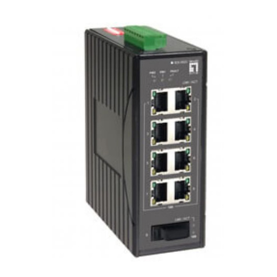
Page 7: Physical Ports
Physical Ports This switch provides: Eight 10/100Base-TX ports Eight 10/100Base-TX ports + one 100Base-FX/BX port Six 10/100Base-TX ports + two 100Base-FX/BX ports Four 10/100Base-TX ports + four 100Base-FX/BX ports Connectivity RJ-45 connectors SC or ST connector on 100Base-FX fiber port SC connector on 100Base-BX fiber port IES-0920 User Manual Page 6... -
Page 8: Installation
Installation This chapter gives step-by-step instructions about how to install the switch: Selecting a Site for the Switch As with any electric device, you should place the switch where it will not be subjected to extreme temperatures, humidity, or electromagnetic interference. Specifically, the site you select should meet the following requirements: ·... -
Page 9: Din Rail Mounting
DIN Rail Mounting Fix the DIN rail attachment plate to the back panel of the switch. Installation: Place the switch on the DIN rail from above using the slot. Push the front of the switch toward the mounting surface until it audibly snaps into place. Removal: Pull out the lower edge and then remove the switch from the DIN rail. -
Page 10: Connecting To Power
Connecting to Power Redundant DC Terminal Block Power Inputs or 12VDC DC Jack (Optional) Redundant DC Terminal Block Power Inputs There are two pairs of power inputs can be used to power up this device. You need to have two power inputs connected to run the device, but the FAULT LED indicator will light up to remind that the power redundant system functions abnormal in case either PWR1 or PWR2 is dead. - Page 11 12VDC DC Jack Input (Optional) Step 1: Connect the supplied AC to DC power adapter to the receptacle on the topside of the switch. Step 2: Connect the power cord to the AC to DC power adapter and attach the plug into a standard AC outlet with the appropriate AC voltage.
- Page 12 Alarms for Power and Port Failure Step 1: There are two pins on the terminal block are used for power failure detection. It provides the normally closed output when the power source is active. Use this as a dry contact application to send a signal for power failure detection. This DIP Switch features the Port Fault Detection;...
-
Page 13: Connecting To Your Network
Connecting to Your Network Cable Type & Length It is necessary to follow the cable specifications below when connecting the switch to your network. Use appropriate cables that meet your speed and cabling requirements. Cable Specifications Speed Connector Port Speed Cable Max. -
Page 14: Specifications
Specifications Ethernet Switch 10/100Base-TX auto-negotiating ports with RJ-45 connectors, 100Base-FX/BX fiber ports Applicable Standards IEEE 802.3 10Base-T IEEE 802.3u 100Base-TX/FX Switching Method Store-and-Forward Forwarding Rate 10Base-T: 10 / 20Mbps half / full-duplex 100Base-TX: 100 / 200Mbps half / full-duplex 100Base-FX/BX: 200Mbps full-duplex Performance 14,880pps for 10Mbps... - Page 15 EN61000-6-2: EN61000-4-2 (ESD Standards) EN61000-4-3 (Radiated RFI Standards) EN61000-4-4 (Burst Standards) EN61000-4-5 (Surge Standards) EN61000-4-6 (Induced RFI Standards) EN61000-4-8 (Magnetic Field Standards) Environmental Test Compliance IEC60068-2-6 Fc (Vibration Resistance) IEC60068-2-27 Ea (Shock) IEC60068-2-32 Ed (Free Fall) NEMA TS1/2 Environmental requirements for traffic control equipment IES-0920 User Manual Page 14...
-
Page 16: Appendix A - Connector Pinouts
Appendix A – Connector Pinouts Pin arrangement of RJ-45 connectors: RJ-45 Connector and Cable Pins The following table lists the pinout of 10/100Base-TX ports. Standard Port Uplink Port Output Transmit Data + Input Receive Data + Output Transmit Data - Input Receive Data - Input Receive Data + Output Transmit Data +...
Need help?
Do you have a question about the Infinity IES-0920 and is the answer not in the manual?
Questions and answers