
Related Manuals for LevelOne IES-0842


Summary of Contents for LevelOne IES-0842
-
Page 1: User Manual
IES-0842 4 x 802.3at PoE + 4 FE Web Smart Switch -10 to 60C, DIN-rail User Manual v1.00 - 1206... - Page 2 Preface This manual describes how to install and use the Industrial Web-Smart PoE & High Power PoE Ethernet Switch. This switch introduced here is designed to deliver full scalability with web-based management functions. Capable of operating at temperature extremes of -40°C to +75°C, this is the switch of choice for harsh environments constrained by space.
-
Page 3: Table Of Contents
Table of Contents OVERVIEW ........................... 4 ..................... 4 NDUSTRIAL MART THERNET WITCH ................................5 EATURES ............................. 5 ACKAGE ONTENTS ............................6 RONT ANEL ISPLAY ................................ 7 OWER NPUT ..............................8 RAIN OUNT 10/100B -TX C ..........................9 ONNECTOR WEB MANAGEMENT ......................10 ............................... -
Page 4: Overview
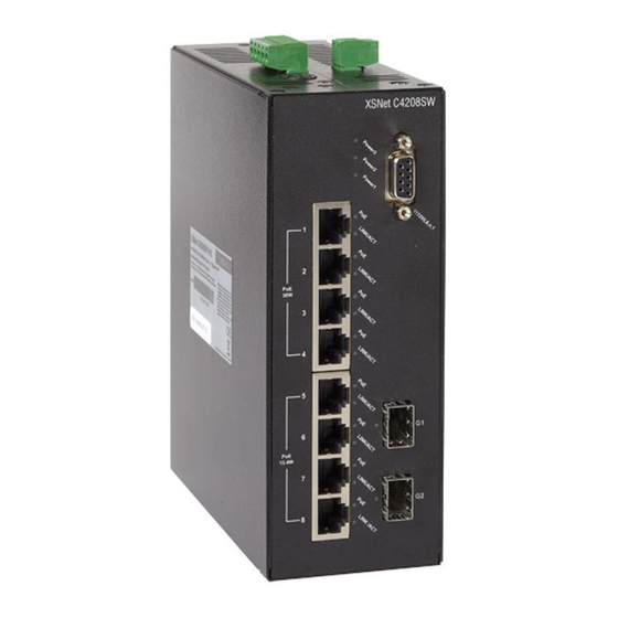
Overview Industrial Web-Smart PoE Ethernet Switch LevelOne IES-0842 Industry Ethernet Switch provides 4 PoE ports of 10/100Base-TX plus 4 ports of 10/100Base-TX Ethernet to enable high speed network at mission-critical environment. This device is designed to be mounted on an industry standard DIN-rail, plus the clearly visible status LEDs provide simple monitoring of port link activity. -
Page 5: Features
When you unpack the product package, you shall find the items listed below. Please inspect the contents, and report any apparent damage or missing items immediately to your authorized reseller. IES-0842 Industrial Web-Smart PoE Ethernet Switch Quick Installation Guide ... -
Page 6: Front Panel Display
Front Panel Display Status Description Steady Power On PW 1,2,3 Power Off 10/100Base-TX or 100Base-FX/BX Steady Network connection is established LNK/ACT Flashing Transmitting or Receiving data Steady Power Device (PD) is connected (High Power) Power Device (PD) is disconnected... -
Page 7: Power Input
Power Input 48VDC Power Ground 48VDC Power Ground Earth Ground 0.1A @ 24VDC Relay Output *Warning signal disable for following: 1. The relay contact closes if Power1 and Power2 are both failed but Power3 2. The relay contact closes if Power3 is failed but Power1 and Power2 are both on. -
Page 8: Din Rain Mount
DIN rain Mount Fix the DIN rail attachment plate to the back panel of the switch. Installation: Place the switch on the DIN rail from above using the slot. Push the front of the switch toward the mounting surface until it audibly snaps into place. ... -
Page 9: 10/100Base-Tx Connector
10/100Base-TX Connector The following lists the pin-out of 10/100Base-TX ports. PoE Port (1 to 4) Standard Port (5) Output Transmit Data + Input Receive Data + Output Transmit Data - Input Receive Data - Input Receive Data + Output Transmit Data + Positive (VCC+) Positive (VCC+) Input Receive Data -... -
Page 10: Web Management
Web Management The switch provides a browser interface that lets you configure and manage the switch remotely. applications directly in your web browser by entering the IP address of the switch. You can then use your web browser to list and manage switch configuration parameters from one central Web-Based Browser Management The switch provides a web-based browser interface for configuring and managing the switch. -
Page 11: Logging On To The Switch
Logging on to the switch Switch IP Address In your web browser, specify the IP address of the switch. Default IP address is 192.168.1.10. User name Enter the factory default user name: admin. Password Enter the factory default password (no password). Or enter a user-defined password if you followed the instructions later and changed the factory default password. -
Page 12: Browser Interface
Browser Interface The web browser interface provides groups of point-and-click buttons at the left field of the screen for configuring and managing the switch. PORT BASED VLAN PRIORITY DIFF SERV CODE POINT Bit 0 ~ 31, Bit 32 ~ 63 ... -
Page 13: Poe
1. System power budget: System power budget and type a new system power budget. 2. OK: OK button to update your settings. 3. Enable mode: C Enable mode drop-down menu to choose Enable or Disable Enable mode drop-down list to enable or disable Port 1 ~ Port 4 to discover Powered Device (PD) connected to Port 1 ~ Port 4 of the Switch. -
Page 14: High Power Poe Operation
High Power PoE Operation This Industrial Web-Smart PoE & High Power PoE Ethernet switch is compliant with the 802.3af and 802.3at High Power standard, providing 30W of pure power to power demanding devices such as pan-tilt-zoom (PTZ) network cameras, wireless access bridge/routers and large-screen network video phones et cetera. -
Page 15: Port Based Vlan
Port Based VLAN Port Based VLAN 1. VLAN.1 ~ VLAN.7: Click and choose Port 1 ~ Port 8 to be added into VLAN.1 ~ VLAN.7. 2. Cancel: Cancel button to cancel your settings. 3. OK: OK button to update your settings. -
Page 16: Priority
Priority Priority 1. Ratio Scheme: Click and choose All High Before Low , 10:1 , 5:1 , or 2:1 ratio scheme. 2. Port 1 ~ Port 8: Click and choose TOS , 802.1p , or Port Priority ( High or Low ) for Port 1 ~ Port 8. -
Page 17: Diff Serv Code Point
Diff Serv Code Point Diff Serv Code Point Bit 0 ~ 31: 1. Diff Serv Code Point: Check and set Bit 0 ~ 31 of Diff Serv Code Point to high priority. 2. Cancel: Cancel button to cancel your settings. 3. -
Page 18: System Setup
System Setup System Setup System Configuration: 1. DHCP Client: Click and choose Enable or Disable to enable or disable the Switch as DHCP client to be automatically supplied an IP address, gateway address, and subnet mask from DHCP server. 2. IP Address: C IP Address text box and type a new address to change the IP Address. -
Page 19: Firmware Upgrade
Firmware Upgrade Firmware Update 1. Cancel: C Cancel button to cancel firmware update request. 2. Update: C Update button and wait for firmware update request being processed. -
Page 20: Specifications
Specifications Applicable Standards IEEE802.3 10Base-T IEEE802.3u 100Base-TX/FX Store-and-Forward Switching Method Forwarding Rate 10 / 20Mbps half / full-duplex 10Base-T 100Base-TX 100 / 200Mbps half / full-duplex 100Base-FX/BX 200Mbps full-duplex Performance 14,880pps for 10Mbps 148,810pps for 100Mbps Cable 4-pair UTP/STP Cat. 3, 4, 5 Up to 100m (328ft) 10Base-T 4-pair UTP/STP Cat.
Need help?
Do you have a question about the IES-0842 and is the answer not in the manual?
Questions and answers