
Related Manuals for Clarke ECP15A1


Summary of Contents for Clarke ECP15A1
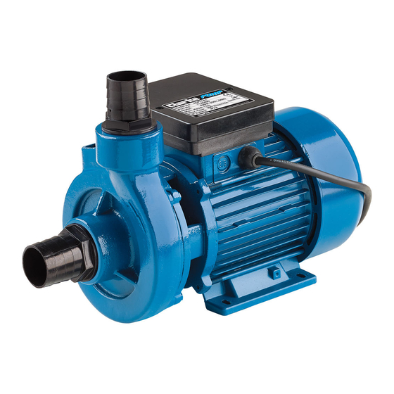
- Page 1 1.5” ELECTRIC WATER PUMP MODEL NO: ECP15A1 PART NO: 7120400 OPERATION & MAINTENANCE INSTRUCTIONS ORIGINAL INSTRUCTIONS GC1020 REV-3...
- Page 2 WHENEVER THERE IS A RISK OF PERSONAL INJURY. ENSURE THAT THESE WARNINGS ARE READ AND UNDERSTOOD AT ALL TIMES. Your CLARKE water pump has been designed to give long and trouble free service. If, however, having followed the instructions in this booklet carefully, you encounter problems, take the unit to your local Clarke dealer.
-
Page 3: General Safety Precautions
9. NEVER modify this pump in any way. Use it ONLY for the purpose for which it is designed. 10. ALWAYS have the pump serviced by your local Clarke dealer, using only identical replacement parts. This will ensure the safety of the pump is maintained. -
Page 4: Electrical Installation
Because of the number of possible installations, no accessories are supplied with your pump except for a pair of male inlet/outlet adaptors. However accessories are available from your nearest Clarke dealer. See the suggested list on page 13. NOTE: It is recommended that the end user should consult a qualified installer if there are any doubts as to the suitability of this product for a particular installation. -
Page 5: Electrical Connections
ELECTRICAL CONNECTIONS WARNING! READ THESE ELECTRICAL SAFETY INSTRUCTIONS THOROUGHLY BEFORE CONNECTING THE PRODUCT TO THE MAINS SUPPLY. Before switching the product on, make sure that the voltage of your electricity supply is the same as that indicated on the rating plate. This product is designed to operate on 230VAC 50Hz. -
Page 6: Pipe/Hose Connections
PIPE/HOSE CONNECTIONS The pump inlet and discharge ports ½ are both 1 ” BSP (38 mm) female threads and accept the adaptors supplied. Hoses with the same diameter should be used and secured to the adaptor with a suitable hose clip. Ensure all connections are air tight when under pressure but not so tight as to crack the plastic inlet/outlet adaptors. -
Page 7: Suction Lift Or Gravity Feed
SUCTION LIFT OR GRAVITY FEED There are two possible methods of pipework installation. 1. Suction Lift. Used to draw clean water from a pool or well providing the vertical distance between the foot valve and the pump does not exceed the 8 metres specified for this pump. -
Page 8: Priming The Pump
PRIMING THE PUMP Before using the pump for the first time the inlet (suction) side must be filled with water to prime the pump as follows:- 1. With all inlet pipes/hoses, but no outlet hose connected, pour water into the outlet port until all the air is expelled. -
Page 9: Operation
1. Do not allow the pump to run dry, otherwise the seal between the pump and motor may be damaged. If a leak occurs at this point, allowing water to pass from the pump to the motor, take the pump to your Clarke dealer for overhaul. -
Page 10: Maintenance
Re-prime the pump when returning to service. • In the event that overhaul of the pump or motor is necessary, contact your Clarke service department. ENVIRONMENTAL RECYCLING POLICY Through purchase of this product, the customer is taking on the obligation to deal with the WEEE in accordance with the WEEE regulations in relation to the treatment, recycling &... -
Page 11: Troubleshooting
Tighten as required. Air leaks through Renew seal. damaged seal. Impeller damaged and Return to your Clarke making poor seal. dealer for repair Impeller / mechanical Return to your Clarke seal is badly worn. dealer for repair. - Page 12 Installation of pump is Stop pump and unstable. re-position. Air pocket in pump or Release plug in impeller pipeline. housing to release air. Damaged impeller Return to your Clarke dealer for repair. Parts & Service: 020 8988 7400 / E-mail: Parts@clarkeinternational.com or Service@clarkeinternational.com...
-
Page 13: Specification
SPECIFICATION Water Classification Clean Maximum Delivery 239 l/min (14.3m /hr) Rated Head 2-14 m Maximum Suction Lift Operating Temperature 0-40 Ingress Protection Rating IP 4 (splashing water) Duty Cycle S1 Continuous Supply 230V / 50Hz Rated Input Power 800W Outlet Thread Size 1.5”... -
Page 14: Parts Diagram
PARTS DIAGRAM ID DESCRIPTION ID DESCRIPTION ID DESCRIPTION Charge Plug Spacer Grounding Mark O-Ring Bearing Screw Pump Casing Spring Washer Cable Clamp Bolt Terminal Cover Spring Washer Motor Housing Gland Washer Screw Stator Winding Capacitor Rotor Impeller Terminal Box Circlip Circlip Screw Back Cover... -
Page 15: Declaration Of Conformity
DECLARATION OF CONFORMITY Parts & Service: 020 8988 7400 / E-mail: Parts@clarkeinternational.com or Service@clarkeinternational.com...
Need help?
Do you have a question about the ECP15A1 and is the answer not in the manual?
Questions and answers