
Related Manuals for Clarke PW80A


Summary of Contents for Clarke PW80A
- Page 1 PETROL DRIVEN WATER PUMP MODEL NO: PW80A PART NO: 7140671 OPERATION & MAINTENANCE INSTRUCTIONS ORIGINAL INSTRUCTIONS GC0819 - ISS1...
-
Page 2: Environmental Recycling Policy
GUARANTEE This CLARKE product is guaranteed against faulty manufacture for a period of 12 months from the date of purchase. Please keep your receipt as proof of purchase. -
Page 3: Safety Precautions
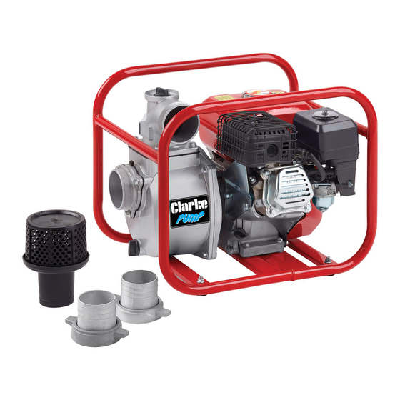
SAFETY PRECAUTIONS CAUTION: As with all machinery, there are certain hazards involved with the operation and use of this water pump. Exercising caution will reduce the risk of personal injury. 1. ALWAYS observe all safety precautions for the handling of fuel. 2. - Page 4 20 Oil Filler and Dipstick 21 Rubber feet/fixings The PW80A petrol driven pump is designed for pumping clean water, or water containing small solids in suspension. The pump is fitted with an open impeller. The suction strainer supplied must always be used to ensure that large stones or other objects cannot be drawn up, as this would cause severe damage to the pump.
-
Page 5: Before Use
BEFORE USE The pump is supplied with four rubber feet. Use the retaining nuts to secure these to the base of the frame. Stand the pump on a firm foundation as near to the water source as possible. Ensure there is adequate drainage for the discharged water and that there is no danger of damage to property as a result of water being discharged. - Page 6 GENERAL USE OF THE PUMP 1. Connect the suction and discharge hoses to the pump housing using the hose clamps and gaskets supplied to achieve an airtight seal. There must be no damage of any kind to the hoses which must be well protected and supported.
-
Page 7: Operation
also be necessary to vent the top of the pump so that air can be expelled during automatic re-priming. Properly fuelled and lubricated your pump will run without further attention. OPERATION WARNING: WHEN THE ENGINE IS RUNNING THE EXHAUST MUFFLER IS VERY HOT. -
Page 8: Shutting Down
• Clearance should be 0.70- 0.80mm. • The recommended spark plug for the PW80A pump is LD F7RTC. Parts & Service: 020 8988 7400 / E-mail: Parts@clarkeinternational.com or Service@clarkeinternational.com... -
Page 9: Changing The Oil
CHANGING THE OIL The oil in the engine should be changed after the first 20 hours use and thereafter every 6 months or 100 running hours. Remove the dipstick and drain plug and then drain the oil. Re-fill and check the level as described on page 5. CAUTION: PROLONGED EXPOSURE TO USED OIL IS HARMFUL. -
Page 10: Troubleshooting
TROUBLESHOOTING Problem Cause Solution Engine fails to start Lack of fuel in the tank Fill the tank as necessary No fuel reaching the Fuel valve is closed. carburetor Engine switch is in the Off Set the engine switch to the position On position. -
Page 11: Component Parts - General
Problem Cause Solution Low output from Engine speed too low. Increase the engine speed. pump Impeller clogged Clean the strainer and ensure it is not submerged in mud or sediment etc. Suction or delivery line Clear any obstruction and obstructed. ensure there are no kinks in the delivery line. - Page 12 ENGINE COMPONENTS DIAGRAM Parts & Service: 020 8988 7400 / E-mail: Parts@clarkeinternational.com or Service@clarkeinternational.com...
- Page 13 ENGINE COMPONENTS LIST ESCRIPTION ESCRIPTION Flange bolt M6 x 8 Flywheel key Recoil starter 31 Connecting rod lever Flange bolt M6 x 12 32 Connecting rod bolt Fan cover 33 Crankcase gasket Flywheel nut M14 x1.5 34 Dipstick Starting cup 35 Dipstick gasket 36 Low crankcase cover Flywheel...
- Page 14 ENGINE COMPONENTS LIST (CONT) ESCRIPTION ESCRIPTION Valve spring 88 Nut M6 Spark plug 89 Low tension lead Flange bolt M6 x12 90 Fuel filler cap Cylinder head cover 91 Fuel filter Cylinder head cover gasket 92 Fuel tank Rocker nut 93 Flange bolt M6 x 25 Rocker adjusting nut 94 Fuel outlet /gasket...
- Page 15 PUMP COMPONENTS DIAGRAM Parts & Service: 020 8988 7400 / E-mail: Parts@clarkeinternational.com or Service@clarkeinternational.com...
- Page 16 PUMP COMPONENTS LIST Description Description Pipe joint gland nut Small gasket Pipe joint O-type sealing ring-1 Pipe joint gasket Guide flow cover Bolt M10 x 20 Bolt M8 x 25 Water inlet flange Pump impeller Check valve Flat key 5 x 18 Outlet flange gasket Bolt M8 x 55 Discharge water joint...
-
Page 17: Specifications
SPECIFICATIONS Item Spec Engine Model PT170F Engine Type 4-stroke OHV single cylinder with forced air cooling Motor HP 6.0 HP (4.6kw) Rotational velocity 3600 rpm Fuel tank Capacity 3.6 L Oil Capacity 0.6 L Fuel consumption 0.86 l/h (1.5 hours on full tank) Guaranteed sound power 106 LWA dB Sound power level... -
Page 18: Declaration Of Conformity
DECLARATION OF CONFORMITY Parts & Service: 020 8988 7400 / E-mail: Parts@clarkeinternational.com or Service@clarkeinternational.com... - Page 19 DECLARATION OF CONFORMITY Parts & Service: 020 8988 7400 / E-mail: Parts@clarkeinternational.com or Service@clarkeinternational.com...
Need help?
Do you have a question about the PW80A and is the answer not in the manual?
Questions and answers