
Related Manuals for Clarke EBP1100


Summary of Contents for Clarke EBP1100
- Page 1 ELECTRIC BOOSTER SURFACE PUMP MODEL NO: EBP1100 PART NO: 7239200 OPERATION & MAINTENANCE INSTRUCTIONS ORIGINAL INSTRUCTIONS GC0819 ISS 1...
-
Page 2: Environmental Recycling Policy
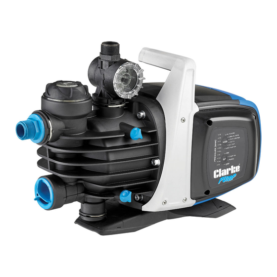
INTRODUCTION Thank you for purchasing this CLARKE 1100W surface booster pump. This non-submersible centrifugal pump is designed to pump clean water in gardens for spraying and irrigation purposes and for pumping water to greenhouses. It can also be used for boosting running water feed pressure (not drinking water) or for pumping out wells or ponds. -
Page 3: Specification
SPECIFICATION Water Classification Clean Maximum Delivery 62.5 l/min Maximum Head 45 m Maximum Suction Lift Operating Temperature 0-35 Ingress Protection Rating IPx4 Supply 230V ~ 50Hz Rated Power 1100 W Input Current@ Maximum Head 4.2 A Outlet Thread Size 1” BSP Weight 10.5 kg Length x Width x Height... -
Page 4: General Safety Precautions
8. NEVER use for pumping flammable liquids or corrosive chemicals. This pump is designed to pump clean water only. 9. ALWAYS have the pump serviced by your local CLARKE dealer, using only identical replacement parts. This will ensure the safety of the pump is maintained. - Page 5 10. Handle Because of the number of possible installations, no accessories are supplied with your pump but a selection is available from your CLARKE dealer. See page 21. NOTE: It is recommended that the end user should consult a qualified CLARKE installer if there are any doubts as to the suitability of this product for a particular installation.
-
Page 6: Installation Of The Pump
INSTALLATION OF THE PUMP IMPORTANT: The pump MUST NOT be connected to the mains power supply until all hose/pipe installations are completed. LOCATION Install the pump in a horizontal position i.e. with the outlet connection facing vertically upwards. Mount the pump on blocks or a purpose built platform to protect it from flooding. -
Page 7: Suction Lift Or Gravity Feed
In case of a fixed installation, it is recommended that you fit a non- return valve on both sides of the pump. This allows closure of the line upstream and/or downstream from the pump, useful for service and cleaning operations or for periods in which the pump is not in use. -
Page 8: Electrical Installation
ELECTRICAL INSTALLATION WARNING: READ THESE ELECTRICAL SAFETY INSTRUCTIONS THOROUGHLY BEFORE CONNECTING THE PRODUCT TO THE MAINS SUPPLY. Connect the mains lead to a standard, 230 Volt (50Hz) electrical supply through an approved 13 amp BS 1363 plug or a suitably fused isolator switch. If the plug has to be changed because it is not suitable for your socket, or because of damage, it must be removed and a replacement fitted, following the wiring instructions shown below. - Page 9 ELECTRONIC CONTROL INTERFACE The EBP1100 electronic system incorporates the following controls: (A) PRESSURE INDICATOR LEDS 10 LEDs are used for indicating pressure from 0 to 6 bar. (B) MODE SELECTION BUTTON Selectable modes include: 1. AUTO_MODE; 2. MANUAL_MODE; 3. ANTI-LEAKAGE;...
- Page 10 USING THE MODE SELECTION BUTTON (B) 1. To unlock the choice of functions press “MODE” button for 5 seconds. 2. Press “MODE” to scroll through the various operating modes or parameters to be modified or to enable certain functions. • While scrolling through the modes, the LED of the function selected will flash.
- Page 11 6) MAX PUMP ON: This is the maximum period of operation. The function can be enabled or disabled. The factory setting is disabled. When enabled, if the pump operates for more than 30 minutes it will be stopped. No error indication is displayed. This function is used to protect the installation if a valve is accidentally left open, or in the event of breakage of a pipe, or in applications for irrigation.
-
Page 12: Description Of The Control Functions
DESCRIPTION OF THE CONTROL FUNCTIONS 1) PUMP ON/OFF (AUTO MODE, MANUAL MODE) CUT-OUT is disabled after the LED test and the pump switches on for 10 seconds. CUT-OUT is enabled after the power plug is inserted, the test is conducted on the LEDs for the first 3 sec (LED 0 indicates that the power is On) and the “AUTO MODE”... -
Page 13: Dry Running Protection
6) ALARMS INDICATION A steady red light or button on “ALARM” is activated when an alarm is present. • Dry-running: steady red light • Leakage: slow pulse • Max Pump ON (pump running for more than 30 minutes): 2 quick flashes separated by a longer pause. -
Page 14: Modes Of Operation
MODES OF OPERATION INITIAL START UP SELF TEST OF LEDS When the pump is plugged into the power supply, a self-test is conducted on the LEDs, during which all the LEDs will light up in sequence for a few seconds. INITIAL PRIMING The pump will automatically be in AUTO mode set to ON. -
Page 15: Normal Operation
NORMAL OPERATION PRIMING THE PUMP 1. Open any valves in the pipeline. 2. Before starting, check that the pump is properly primed. Fill it completely with clean water after having removed the cap above the transparent filter (1). • A special wrench is provided for this. -
Page 16: Care During Use
1. DO NOT allow the pump to run dry, otherwise the seal between the pump and motor may be damaged. If a leak occurs at this point, allowing water to pass from the pump to the motor, take the pump to your Clarke dealer for overhaul. -
Page 17: Maintenance And Cleaning
The pump should not be taken apart by the user if overhaul is required, but should be taken to your nearest CLARKE dealer for repair. CLEANING THE SUCTION FILTER 1. Switch off the electric power supply to the pump. -
Page 18: Troubleshooting
Tighten as required. Air leaks through Renew seal. damaged seal. Impeller damaged and Return to your CLARKE making poor seal. dealer for repair. Impeller / mechanical Return to your CLARKE seal is badly worn. dealer for repair. - Page 19 Installation of pump is Stop pump and unstable. re-position. Air pocket in pump or Release plug in impeller pipeline. housing to release air. Damaged impeller Return to your CLARKE dealer for repair. Parts & Service: 020 8988 7400 / E-mail: Parts@clarkeinternational.com or Service@clarkeinternational.com...
-
Page 20: Component Parts - General
COMPONENT PARTS - GENERAL Parts & Service: 020 8988 7400 / E-mail: Parts@clarkeinternational.com or Service@clarkeinternational.com... - Page 21 COMPONENT PARTS LIST (GENERAL ASSEMBLY) ID DESCRIPTION ID DESCRIPTION Body assembly Capacitor clip Motor assembly Cable clamp O-ring Cable Motor position case Carrying handle O-ring Motor cover Screws Motor cover top cap Drainage pipe Motor cover plug O-ring Pump base assembly O-ring Sensor assembly O-ring...
- Page 22 COMPONENT PARTS-PUMP ONLY Pump body O-ring Inlet connector O-ring Inner valve body O-ring Non-return valve Venturi assembly Filter with base Filter cap Diffuser O-ring Plug Pump body plug Fork Fork O-ring O-ring Parts & Service: 020 8988 7400 / E-mail: Parts@clarkeinternational.com or Service@clarkeinternational.com...
-
Page 23: Declaration Of Conformity
DECLARATION OF CONFORMITY Parts & Service: 020 8988 7400 / E-mail: Parts@clarkeinternational.com or Service@clarkeinternational.com...
Need help?
Do you have a question about the EBP1100 and is the answer not in the manual?
Questions and answers