
Related Manuals for Clarke PW50


Summary of Contents for Clarke PW50
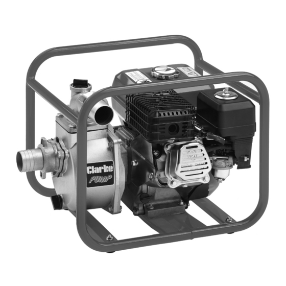
- Page 1 ENGINE DRIVEN 2” PUMP MODEL NO: PW50 PART NO: 7140650 OPERATION & MAINTENANCE INSTRUCTIONS GC0816...
-
Page 2: Environmental Protection
INTRODUCTION Thank you for purchasing this CLARKE Pump. This pump is designed for pumping clean or dirty water, that is water containing solids in suspension. It is NOT designed for pumping slurry, sludge, mud or heavily polluted water, or any water containing chemicals or other acidic contaminants including salt water. -
Page 3: General Safety Rules
GENERAL SAFETY RULES WARNING: WHEN USING POWERED PRODUCTS, BASIC SAFETY PRECAUTIONS SHOULD ALWAYS BE FOLLOWED TO REDUCE THE RISK OF FIRE, ELECTRIC SHOCK AND PERSONAL INJURY. READ ALL THESE INSTRUCTIONS BEFORE ATTEMPTING TO OPERATE THIS PRODUCT AND SAVE THESE INSTRUCTIONS FOR FUTURE REFERENCE. 1. -
Page 4: General Safety In The Workplace
CARE OF PUMPS 1. A component that is damaged should be properly repaired or replaced by your Clarke service department. 2. Always check for any damage or any condition that could affect the operation of the pump. Damaged parts should be properly repaired. - Page 5 Sealing Rings The items above should be supplied in the carton. If any items are missing or damaged, please contact the Clarke dealer where you purchased the product. The pump is fitted with an open impeller. The suction strainer supplied, must always be used, to ensure that large stones or other objects cannot be drawn up, as this would cause severe damage to the pump.
-
Page 6: Before Use
BEFORE USE FITTING THE FEET 1. Fit the 4 x rubber feet to the frame using the nuts and washers supplied. FILLING WITH OIL This pump is not supplied containing engine oil or fuel. Use any engine oil of SAE 10-30 rating unless operating at very high or low ambient temperatures. -
Page 7: Installing The Pump
INSTALLING THE PUMP 1. Position the pump on a firm foundation and as near to the water source as possible. 2. Connect the suction and discharge hoses to the pump using the hose clamps and sealing rings supplied, to achieve an airtight seal. - Page 8 4. Attach the inlet strainer to the end of suction hose using a further hose clamp, to prevent large stones etc, from being drawn up which could cause severe damage. Keep the strainer free of debris. 5. If it is likely to clog with dirt or debris, proceed by either: •...
-
Page 9: Operation
OPERATION WARNING: WHEN THE ENGINE IS RUNNING THE EXHAUST MUFFLER IS VERY HOT. TAKE CARE TO AVOID BURNS. NEVER RUN THE ENGINE IN AN ENCLOSED SPACE - ENSURE THERE IS ADEQUATE VENTILATION. Ensure the site and pump are prepared, then proceed as follows: STARTING •... -
Page 10: Shutting Down
With a suction lift of 5 to 10ft, the pump should begin discharging liquid in a few moments. To further reduce priming time, the engine speed may be increased after the engine is properly run in. If pumping does not start within this time, shut off engine and check carefully to find the problem. -
Page 11: Changing The Oil
5. Replace the spark plug after the first month or every 50 hours of use. 6. Check when installing that the spark plug has the correct clearance by measuring with a feeler gauge and adjusting the side electrode as required. •... -
Page 12: Troubleshooting
3. Pull the starter recoil rope slowly 2 or 3 times so that the oil is deposited on the cylinder walls and replace the spark plug. • Suction and delivery hoses, additional connectors and filters are available froom your Clarke stockist. TROUBLESHOOTING PROBLEM... - Page 13 Dismantle pump and replace impeller. If, after reading the troubleshooting chart you are still unable to rectify any faults, please contact your local dealer or Clarke International for assistance. Parts & Service: 020 8988 7400 / E-mail: Parts@clarkeinternational.com or Service@clarkeinternational.com...
-
Page 14: Specification
SPECIFICATION Item Spec Product dimensions (L x W x H) 470 x 375 x 400 mm Product Weight (kgs) 23.3 kg Water classification Dirty/Clean Max solids in suspension 4 mm Inlet/Outlet Size 2” BSP Maximum Flow 550 l/min (33m Max Head 30 m Suction Head Max Pressure... -
Page 15: Component Parts - Engine Assembly
COMPONENT PARTS - ENGINE ASSEMBLY No Description No Description Fuel Tank Cover Air Deflector Fuel Strainer Oil Drain Plug Fuel Tank Gasket Tension Spring M6 x 12 Bolt Governor Arm Suppressor Nut M6 Crankcase Gasket Governor Lever Oil proximity Sensor Governor Rod Bolt M6 x 15 Governor Spring... - Page 16 Bolt Rocker Arm Gasket Muffler Cover Carburetor Rocker Bolt Gasket Pushrod retainer Frame Fixing plate Pushrod Gasket Exhaust Gasket Stud Cable Bracket Cylinder Head Screw Cylinder Head Gasket Bolt Exhaust Valve Circlip Inlet Valve Connecting Rod Tappet Muffler Camshaft Nut M8 Rubber Tube Compression Ring Exhaust Valve Adjusting Nut...
- Page 17 COMPONENT PARTS - ENGINE ASSEMBLY Parts & Service: 020 8988 7400 / E-mail: Parts@clarkeinternational.com or Service@clarkeinternational.com...
-
Page 18: Component Parts - Pump Assembly
COMPONENT PARTS - PUMP ASSEMBLY No Description No Description Locking Collar Washer Hose Adaptor O-Ring Sealing Ring Guide Flow Cover Bolt M8 x 20 M8 x 25 Bolt Water Inlet Flange Pump Impeller Check Valve Flat Key Gasket Bolt M8 x 45 Discharge Elbow Sealing Ring Drain Plug... -
Page 19: Declaration Of Conformity
DECLARATION OF CONFORMITY Parts & Service: 020 8988 7400 / E-mail: Parts@clarkeinternational.com or Service@clarkeinternational.com...
Need help?
Do you have a question about the PW50 and is the answer not in the manual?
Questions and answers