
Subscribe to Our Youtube Channel
Related Manuals for eta Flex


Summary of Contents for eta Flex
- Page 1 2020-09-30 0000000487 V.002 X.49.0 939110-001 Pellet conveyor "Flex" Operating Instructions...
- Page 2 ETA Heiztechnik Gewerbepark 1 A-4716 Hofkirchen an der Trattnach Tel: +43 (0) 7734 / 22 88 -0 Fax: +43 (0) 7734 / 22 88 -22 info@eta.co.at www.eta.co.at...
-
Page 3: Table Of Contents
Contents General ................4 General information . -
Page 4: General
On non-compliance with this safety instruction, there is Copyright a risk of major physical injury. All contents of this document are property of ETA Heiztechnik GmbH and are protected by copyright. Explanation of pictograms Any reproduction, transfer to third parties or use for... -
Page 5: Warranty, Guarantee And Liability
Repair of defects For repairs of defects carried out by the customer or by a third party, ETA shall only bear the costs or remain No leaks in the components, e.g. screw con- obligated by warranty if this work was approved in nection or maintenance cover. -
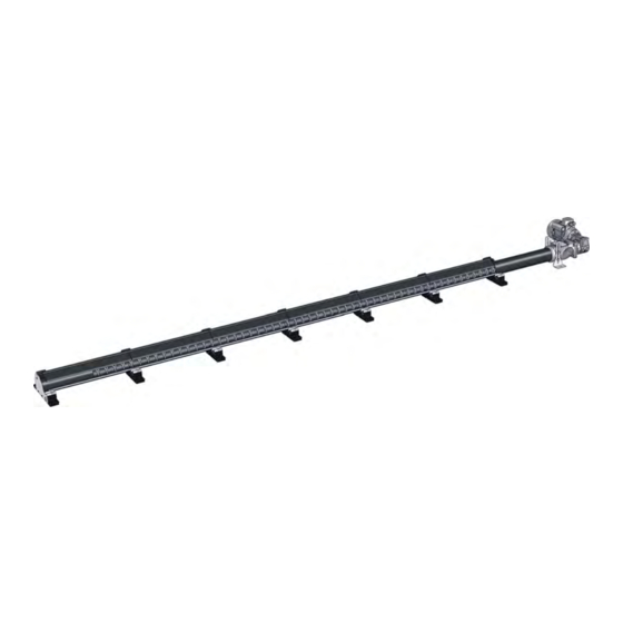
Page 6: Description
Wall duct for maximum 300 mm thick walls (can be shortened on site) Fire protection sleeve (for the wall duct from the pellet store to the installation room) Transfer coupling Conveying system drive Shaftless screw conveyor (can be shortened on site) www.eta.co.at... - Page 7 Description The pipe for the wall duct must protrude a little on each side for the installation of the fire protection sleeve, supporting part and the transfer coupling. This results in storeroom lengths (uncut) in 0.5 m increments. The troughs can be shortened on site, so any storeroom length up to 6 m is possible.
-
Page 8: Note
Fig. 2-6: level out uneven flooring Wooden boards to compensate for height differences can also be laid longitudinally over the whole length. With these varieties the supporting parts can be fastened to the wooden boards, as long as they are Fig. 2-4: Cover plate www.eta.co.at... - Page 9 Description Note sufficiently thick (more than 30 mm). The wooden boards (or panels) themselves are fixed to the floor with suitable screws. The thickness of the wooden boards (or panels) must be taken into account when creating the opening for the wall duct. Storerooms with sealed floors If the conveying system is installed in a storeroom with a sealed floor (i.e,.
-
Page 10: Installation
Also check the floor level inside and outside the storeroom. If the floor level in the storeroom is lower than outside, this must be taken into account when creating the opening for the wall duct. www.eta.co.at... - Page 11 Installation Fasten the support stand to the transfer coupling. Fill the free space between the pipe and opening Initially only hand-tighten the screws. with mineral wool. This serves as sound insulation and fire protection. Fig. 3-5: Support stands Push the pipe for the wall duct into the transfer coupling.
- Page 12 Fig. 3-10: Minimum gap Adjust the height of the support stands so that the transfer coupling is level. Fasten the support stands to the floor with suitable screws. Only hand-tighten the screws. Fig. 3-13: Supporting part Fig. 3-11: Support stand www.eta.co.at...
- Page 13 Installation Check the horizontal alignment of the pipe of the wall All supporting parts must be aligned. Therefore duct. If necessary, place the shim plates supplied measure the gap from the first supporting part to the under the supporting part. wall and mark this distance at the end of the storeroom.
- Page 14 If the troughs are aligned and pushed together using the marking on the floor, fix all supporting parts hand- tight to the floor with suitable screws. For the time Fig. 3-21: Last trough section www.eta.co.at...
- Page 15 Installation Align all troughs horizontally with the washers included the screw conveyor. The length of the cut pieces in the delivery scope. corresponds to the length for shortening the screw conveyor. Fig. 3-22: Aligning horizontally To set this up, you can also stretch a cord Fig.
- Page 16 Fig. 3-28: Screw conveyor drive stub Secure the screw conveyor with the screw and washer and attach the drive to the transfer coupling. Fig. 3-31: Checking the correct distance Fig. 3-29: Drive www.eta.co.at...
- Page 17 Installation If the distance is larger, the screw conveyor must be Screwing all supporting parts to the floor shortened at the end. Position the last supporting part using the marking on the floor. Align the duct horizontally in the longitudinal and transverse directions with the washers.
-
Page 18: Tilted Floor
8.6 "Tilted floor". Fig. 3-38: Fastening the supporting parts Fig. 3-40: Substructure Let the slanted floor rest against the supporting parts and troughs. The integrated seal on the troughs then compensates for any unevenness. Fig. 3-41: Slanted floor www.eta.co.at... - Page 19 Installation Tilted floor The slanted floor can be attached to the supporting A cover plate is also included in the delivery scope for parts. See the following illustration. the front area (for the wall duct). If necessary, the length of the plate can be shortened. Fig.
-
Page 20: Attaching Pellet Hoses
On the ends of both pellet hoses, free around 10 cm of Remove the paint or the coating from both pellet the copper wire strands from the hoses. hose connections. Fig. 3-48: Exposing the copper wire www.eta.co.at... -
Page 21: Pellet Store
Installation Pellet store Pellet store Push both pellet hoses onto the nozzles on the boiler and fasten them with the hose clamps. Connect the copper wires from both pellet hoses to the yellow- Complete the pellet store green earthing cable (next to the nozzles). The set up of the pellet storeroom as well as further helpful advice for the design of the storeroom can be found in chapter... -
Page 22: Configuration
Adding a function block [Standard store] Select the required function block from column [Possible FUBs]: Possible FUBs PE-C 0 Standard store Add the function block and select the following type of conveying system: Type of store: Flex conveying system Save the changes made. www.eta.co.at... -
Page 23: Electrical Connections
Electrical connections Electrical connections Use a 3x1 mm² cable. To avoid damage, it is not Electrical connection must only be made by permitted to turn the shaftless screw conveyor qualified specialist personnel backwards. The electrical installation must only be performed by specialist personnel with the corresponding qualifications. -
Page 24: Concluding Activities
In the function block of the pellet store, switch to the inputs and outputs menu. Select the conveying system screw [Discharge screw] and press the button for manual operation. Only start the conveying system conveyor drive with the [Fwd] button. Fig. 5-4: Menu for manual operation www.eta.co.at... -
Page 25: Etatouch Controller
ETAtouch controller [Pellet store] function block ETAtouch controller [Pellet store] function block Pellet store overview screen Operating condition and information. A description of the operating conditions can be found in the integrated Help menu by pressing the button. Current pellet stock. This is calculated by the control system and can therefore differ by +/- 15% from the actual pellet supply... -
Page 26: Noise Emission
Placement of the storeroom is crucial for satisfactory operation. For this reason, do not place the pellet store underneath or in the immediate vicinity of bedrooms. Because the noises that occur during operation could be transferred into these rooms. www.eta.co.at... -
Page 27: Pellet Store
Placement of the storeroom is crucial for satisfactory all ETA pellet boilers with a rotary valve so that even operation. For this reason, do not place the pellet store during operation there is no open connection between underneath or in the immediate vicinity of bedrooms. -
Page 28: Requirements For Pellet Store
Therefore, the pellet store must be "emptied" at the latest every three years, so that the dust can be removed before refilling. Shovel "old" pellets either to the discharge screw or the suction probe, so that they are quickly used up. www.eta.co.at... -
Page 29: Calculating Pellet Supply And Store Size
Pellet store Calculating pellet supply and store size Calculating pellet supply and The length of the conveying system needed for the storage volume can be determined using table Tab. 8- store size 1: "Useful cross section". That length also determines the minimum length of the storeroom. -
Page 30: Filling Nozzles
500 mm from the wall to prevent damage to both pellets and the plasterwork on the wall. The filling nozzles must be installed 200 mm below the ceiling to keep the pellets from scraping on the ceiling during injection. www.eta.co.at... - Page 31 Each half of the room needs its own nozzle with an impact protection mat on the opposite side. The disad- ETA filling nozzles with 100 mm diameter fit exactly in vantage is that halfway through the filling process, the the cut-outs made for fitting a sewer pipe with 110 mm hoses must be exchanged.
-
Page 32: No Cables/Pipes In The Pellet Store
For filling nozzles and sealing caps available from system. Do not use plastic piping (danger due to ETA, the interior of the sealing caps contain a cover for electrostatic charge build-up). sealing. If this cover is removed, air enters the pellet store via the sealing cover. -
Page 33: Tilted Floor
Pellet store Tilted floor itself may not lean against the walls since the often statically inadequately dimensioned walls do not have the strength to withstand the forces involved. Only explosion-proof electrical installations DANGER! No electrical equipment such as switches, lights, junction boxes, etc. -
Page 34: Information About Pellet Hoses
If the radius is below this value, the cross section of the pellet hose is reduced and the friction on the inner walls increases. As a result, the pellets are damaged, blockages can occur and the service life of the pellet hose is reduced. www.eta.co.at... - Page 35 Pellet store Information about pellet hoses Installation tips for pellet hoses Straight paths Lay out the pellet hoses as straight as possible. Suction hoses laid out in loops have higher friction on the inner walls, which can result in damage to the pellets.
-
Page 36: Fire Safety Regulations
Fire safety regulations in Austria This alarm thermostat is not required for an ETA Legally, fire safety is regulated in the various building pellet system since the ETA rotary valve with... - Page 37 Pellet store Fire safety regulations • no lines through walls, • No other use. • Doors self-closing and fire-resistant EI30 (T30). • Pellet filling lines through other rooms EI90 (F90). Rated heat output of boiler less than 50 kW (boiler room): •...
-
Page 38: Ventilation
Fan with three-times air exchange rate per hour related to the gross volume of the store • The function of the fan is to be coupled with the opening of the store room door Tab. 8-2: Requirements of VDI 3464 www.eta.co.at... - Page 39 Pellet store Ventilation Even if the filling nozzles protrude into a room in which ventilation is available, ÖNORM M 7137 recommends Examples for ventilating the pellet store using only sealed, unventilated sealing covers. Fig. 8-19: Filling nozzles in the boiler room Fig.
- Page 40 DOWNLOAD www.eta.co.at...
Need help?
Do you have a question about the Flex and is the answer not in the manual?
Questions and answers