Advertisement
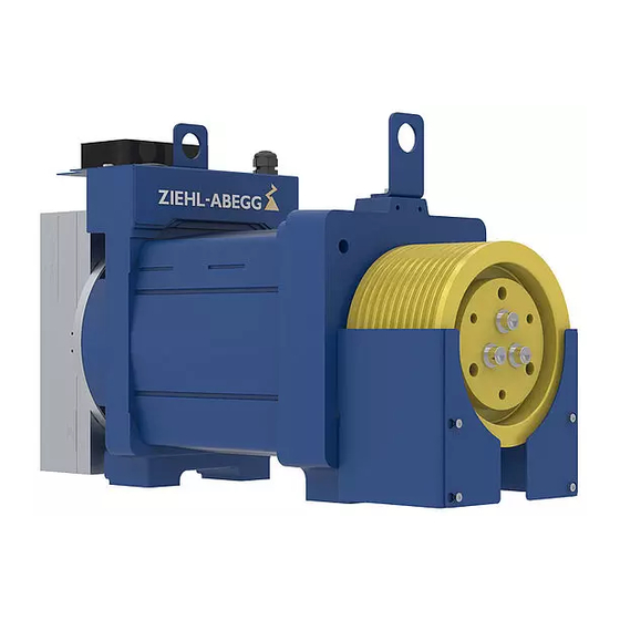
ZAtop SM180 - Retrofitting of forced venti-
lation
1 General information
Forced ventilation installed
1.1
Structure of the assembly instructions
"
The assembly instructions do not replace the original operating instructions for the motor or frequency
inverter. Also observe the original operating instructions.
"
The original operating instructions has to be always available!
2 Safety instructions
2.1
General information
•
ZIEHL-ABEGG SE Spare parts are not ready-to-use products and may only be operated when they have
been installed on an elevator machine and their safety has been assured using guard grilles, barriers,
structural attachments or other appropriate measures, depending on the application (see also
DIN EN ISO 13857)!
•
Only have installation and electrical connection carried out by trained specialist personnel.
•
It is strictly forbidden for work to be carried out on any components while they are connected to live voltage.
The open equipment is protected to IP00. It is possible to come into direct contact with dangerous voltages!
•
Check to ensure voltage is not applied to input terminals prior to commencing work with controller.
•
The terminal box for the forced ventilation must be closed during operation.
Danger!
Warning of hand injuries!
Risk of injury from reaching into the rope guard.
"
Do not carry out any activities during operation.
"
"
Only perform maintenance work on the drive when stopped!
A-TIA20_04-GB 2010 Index 001
Part.-No. 01015846-GB
english
Advertisement
Table of Contents

Subscribe to Our Youtube Channel
Summary of Contents for ZIEHL-ABEGG ZAtop SM180
- Page 1 General information • ZIEHL-ABEGG SE Spare parts are not ready-to-use products and may only be operated when they have been installed on an elevator machine and their safety has been assured using guard grilles, barriers, structural attachments or other appropriate measures, depending on the application (see also DIN EN ISO 13857)! •...
- Page 2 Assembly instructions Scope of delivery 3 Scope of delivery Designation Pos. Count pre-assembled forced ventilation thermostatic switch included insulating tube Cable gland cable tie Insulating hose 4 Tools required General information • Wrench size 10 • Wrench size 17 • Slotted screwdriver 5 Mechanical installation Mounting of the thermostatic switch...
- Page 3 Assembly instructions Mechanical installation 6. Screw the thermostat (2) into the bearing bracket. 7. Guide the connecting cable for the thermostat through the cable gland supplied (item 3). 8. Fit the insulating hose supplied (item 14) on the connecting cable for the thermostat. 9.
- Page 4 Physical data Weight [kg] Customer Service Phone +49 7940 16-308 +49 7940 16-249 drives-service@ziehl-abegg.com Headquarters ZIEHL-ABEGG SE Heinz-Ziehl-Straße • 74653 Künzelsau Germany Phone +49 (7940) 16 16-0 • Fax +49 7940 249-249 drives@ziehl-abegg.de • www.ziehl-abegg.com A-TIA20_04-GB 2010 Index 001 Part.-No. 01015846-GB...


Need help?
Do you have a question about the ZAtop SM180 and is the answer not in the manual?
Questions and answers