Table of Contents
Advertisement
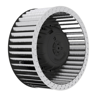
Centrifugal-motorized impellers
Type RE..P / RH..M
Explosion-proof design in compliance with Directive
2014/34/EU (ATEX) for use in zone 1 (category 2) and
zone 2 (category 3) explosive atmosphere
Assembly instructions
L-BAL-F006-GB 2010 Index 002
Keep for reference!
VENTILATOR-Typenschild
einkleben!
Part.-No. 00280361-GB
english
Advertisement
Table of Contents

Related Manuals for ZIEHL-ABEGG RE P Series


Summary of Contents for ZIEHL-ABEGG RE P Series
- Page 1 english Centrifugal-motorized impellers Type RE..P / RH..M Explosion-proof design in compliance with Directive 2014/34/EU (ATEX) for use in zone 1 (category 2) and zone 2 (category 3) explosive atmosphere Assembly instructions Keep for reference! VENTILATOR-Typenschild einkleben! L-BAL-F006-GB 2010 Index 002 Part.-No.
-
Page 2: Table Of Contents
Assembly instructions Centrifugal-motorized impellers Content General notes ..........Structure of the assembly instructions . - Page 3 Assembly instructions Centrifugal-motorized impellers 4.2.4 Sealing ........Connection lead &...
-
Page 4: General Notes
We do not accept any liability for possible errors or omissions in the information con- tained in data, illustrations or drawings provided. ZIEHL-ABEGG SE is not liable for damage due to misuse, improper use or as a consequence of unauthorized repairs or modifications. -
Page 5: Safety
(see rating plate). • The conveyance of solid matter or solids content in the conveying medium is not permissible and can lead to dangerous situations. ZIEHL-ABEGG rejects any liability for damage of any kind as a result of such use. •... -
Page 6: Intended Use
To consider is also the documentation of attached components. • On ZIEHL-ABEGG RE..P / RH..M centrifugal motor impellers from group II, equipment category 2G, EPL Gb with ignition-protection class “c” (with “h” marking) for conveying group IIB explosive gas atmospheres for zone 1 and zone 2, with MK.. external rotor motors for potentially explosive areas, ignition-protection class “e”... -
Page 7: Hazards And Intended Use
Assembly instructions Centrifugal-motorized impellers Safety 2.3 Hazards and intended use 2.3.1 Special hazards when operating in explosive atmospheres When operating a fan in an explosive atmosphere and when conveying explosive gases with the fan, comply especially with the following potential hazards and ignition sources stated below: •... -
Page 8: Explanations Of Symbols
Assembly instructions Centrifugal-motorized impellers Safety • Use as fire gas or smoke extraction fan. • All applications not listed in the intended use. • Fans and parts of fans must never be changed or altered without authorisation. The following measures apply, for instance, as non-intended: –... -
Page 9: Product Safety
Assembly instructions Centrifugal-motorized impellers Safety 2.5 Product safety The device conforms to the state of the art at the time of delivery and is fundamentally considered to be reliable. The device and its accessories must only be used in a flawless condition and installed and operated in compliance with the assembly instructions and/or operating instructions. -
Page 10: Modifications / Interventions In The Device
ZIEHL-ABEGG.These parts were specifically designed for the device. There is no guarantee that parts from non-original sources are designed and manufactured in correspondence with load and safety requirements. Parts and optional equipment not supplied by ZIEHL-ABEGG are not approved by ZIEHL-ABEGG for use. 2.9 Operator’s obligation of diligence •... -
Page 11: Product Overview
Product overview 3 Product overview 3.1 Application / operational area ZIEHL-ABEGG RE..P/RH..M series centrifugal motor impellers (see rating plate for type designation) with explosion-proof design II 2G h IIB T3/T4 Gb with MK type integrated external rotor motor with increased safety ignition protection class II 2G Ex eb IIC T3/T4 Gb, in compliance with IEC 60079-0;... -
Page 12: Motor Impeller Marking
Assembly instructions Centrifugal-motorized impellers Product overview The system manufacturer or operator must ensure that the maximum permitted surface temperature and the temperatures of attached devices do not exceed the T3 or T4 temperature class of the motor impeller and that the ambient air is not above 60 % of the maximum permitted ignition temperature due to the volume flow rate around the motor. -
Page 13: Name Plate
Assembly instructions Centrifugal-motorized impellers Product overview 3.2 Name plate There are two rating plates on the product: 1. The fan rating-plate includes the rated voltage and connection and up to which specifications the fan can be loaded. Values higher than the stamped absorbed power / stamped absorbed wattage mean the fan is operating in a range that is not permitted. -
Page 14: Transport, Storage
Assembly instructions Centrifugal-motorized impellers Product overview 3.3 Transport, storage Attention! • Observe the weight specifications (see rating plate) and the permissible carrying loads of the means of transport. • Wear safety clothing / shoes and cut-resistant safety gloves when handling. •... -
Page 15: Mounting
Assembly instructions Centrifugal-motorized impellers Mounting 4 Mounting 4.1 General notes Attention! • Check the fan for damage, e.g. cracks, dents or damage to the electric cables, before assembly. Start-up is not allowed in the case of transport damage! • Mounting is only to be undertaken by trained service personnel. The system manufacturer or the machine builder and/or the user is responsible that the inherent installation and security information are harmonized with the valid standard and guidelines (EN ISO12100 / 13857). -
Page 16: Special Installation Features For Explosion-Protected Motor Impel- Lers
In terms of material selection, due to special protective measures relating to possible contact surfaces between rotating and stationary components (impeller end plate, cover disk / inlet nozzle), ZIEHL-ABEGG centrifugal motor impellers satisfy the requirements of the EN 14986 standard. -
Page 17: Protect From Contact With Rotating And Stationary Parts
The system manufacturer must ensure that the minimum and maximum gap “U” are adhered to. A copper inlet nozzle can be ordered from ZIEHL-ABEGG SE as an accessory. This complies with the specified material pair. -
Page 18: Sealing
RH56M RH63M The possible contact diameter corresponds to the internal diameter at the aspirating hole in the impeller, which is specified on ZIEHL-ABEGG SE dimension sheets as “DSI” (RE..P) or “DE” (RH..M). Attention! Always check the gap dimension with a feeler gauge before start-up. Safe operation is only guaranteed if it is compliant. -
Page 19: Connection Lead & Terminal Box
Assembly instructions Centrifugal-motorized impellers Electrical installation 4.3 Connection lead & terminal box Information In demanding environments (wet areas, open air installation) all connections must incorporate water drainage curves. To ensure that water cannot penetrate through to the controller housing from the connections install a terminal box lower than the motor. 4.4 Assembly in a humid atmosphere Information If the device is not in use for longer periods in a humid atmosphere, it is recommended to... -
Page 20: Connection
ZIEHL-ABEGG parts lists. The permitted medium temperature is -20...+40 °C. Any differ- ent medium temperatures are specified on the rating plate, the data sheet and the EC type approval certificate. -
Page 21: Mains Connection
EN 60079- may be operated in a partial voltage range. The utilization of electronic or transformer-induced control units, with the exception of frequency converters, is allowed. The use of ZIEHL-ABEGG control units is recommended. Control devices from other manufacturers must have the same or higher quality! ZIEHL-ABEGG offers a comprehensive range of voltage controllers for speed control on 1 ~ and 3 ~ motors. -
Page 22: Start-Up
Assembly instructions Centrifugal-motorized impellers Start-up 6 Start-up 6.1 Prerequisites for commissioning Attention! • During commissioning, unexpected and hazardous conditions can arise in the entire installation due to defective adjustments, defective components or incorrect electrical connections. Remove all persons and objects from the hazardous area. •... - Page 23 • Check the system for resonances. If they lead to unacceptable high vibrations on the motor impeller, the system may not be started up (contact ZIEHL-ABEGG SE service if necessary). • A-rated sound power levels of over 80 dB(A) are possible, see product catalogue.
-
Page 24: Trouble Shooting
Assembly instructions Centrifugal-motorized impellers Trouble shooting • During erection / start-up operation, the ambient temperature, air humidity, environ- mental contamination, and corrosion through the surrounding atmosphere must be taken into consideration. 7 Trouble shooting 7.1 Code of behaviour in the event of faults In the event of faults, which represent a danger to people, installation or environment, "... - Page 25 Check wings/blades for damage, soiling or ice see "Impeller blocked or dirty" Unusual noises Ball bearing damaged / Replacement of the ball bearing by ZIEHL-ABEGG re- worn quired Impeller / blade scrapes / When indicated, clear foreign bodies/dirt from the fan brushes see "Impeller blocked or dirty"...
-
Page 26: Service Work
Repainting can lead to dangerous, static charges and is therefore not permissible! • Bolted-on wheels and/or wings may only be replaced by authorised ZIEHL-ABEGG SE staff. The manufacturer shall not be liable for damage caused through improper repair work. -
Page 27: Cleaning
Assembly instructions Centrifugal-motorized impellers Service work • Regularly check the earth connection of all components. • The system constructor must enable easy access for cleaning and inspection work. • Any faults detected in the electric system/modules/operating equipment must be corrected immediately. If these faults are not corrected, the device/system is potentially very dangerous. -
Page 28: Enclosure
Assembly instructions Centrifugal-motorized impellers Enclosure 9 Enclosure 9.1 Technical data Line voltage 3 ~ 400V +/- 10 %, 50/60 Hz (see rating plate) Duty type of motor/fan Continuous operation with occasional starts (S1) according to DIN EN 60034-1:2011-02. Permissible minimal and maxi- -20 ...40 °C or + 60 °C, see motor rating plate mal ambient temperature for op- eration... -
Page 29: Connection Diagram
Assembly instructions Centrifugal-motorized impellers Enclosure 9.2 Connection diagram Example of possible connection diagram for 3 ~ motor with one speed 3~ Motor mit einer Drehzahl und Temperaturfühler. Drehrichtungsänderung durch Vertauschen von 2 Phasen. 3~ motor with one speed and temperature sensor. Change of direction of rotation by interchanging of 2 phases. -
Page 30: Ec Declaration Of Incorporation
Electronically commutated internal or external rotor motor (also with integrated EC controller) complies with the requirements in Appendix I, Articles 1.1.2, 1.1.5, 1.4.1, 1.5.1 in EG Machinery Directive 2006/42/EG. Manufacturer ZIEHL-ABEGG SE Heinz-Ziehl-Strasse D-74653 Künzelsau The following harmonised standards have been used: EN 60204- Safety of machinery;... - Page 31 It is prohibited to commission this incomplete machine until it has been secured that the machine into which it was incorporated complies with the stipulations of the EC Machinery Directive. Künzelsau, 03.09.2018 (location, date of issue) ZIEHL-ABEGG SE ZIEHL-ABEGG SE Dr. W. Angelis Dr. D. Kappel Technical Director Air Movement Division...
-
Page 32: Eu Declaration Of Conformity
Assembly instructions Centrifugal-motorized impellers Enclosure EU declaration of conformity - Translation - (english) ZA152ex-GB 2007 Index 002 ZIEHL-ABEGG SE Heinz-Ziehl-Straße 74653 Künzelsau Germany The manufacturer hereby declares its sole responsibility that the products • Axial fan: FB…., FV…., DN…. •... - Page 33 Assembly instructions Centrifugal-motorized impellers Enclosure Type Zone Equip- Type of Explosion Temperature Equipment ment protec- group* class* protection class tion level EPL Centrifugal RH... 1 h, (c) IIA, IIB T1,T2,T3,(T4) Gb Centrifugal RH... 2 h, (c) IIA, IIB T1,T2,T3,(T4) Gc Centrifugal RH...
- Page 34 (e.g. control units, guard grilles, etc.), then the manufacturer or operator of the complete system is responsible for compliance with the ATEX Directive 2014/34/EU. Künzelsau, 25.02.2020 (location, date of issue) ZIEHL-ABEGG SE ZIEHL-ABEGG SE Dr. W. Angelis Dr. D. Kappel...
-
Page 35: Index
Assembly instructions Centrifugal-motorized impellers 9.5 Index material combinations air density Assembly ATEX overheating protection ATEX Zone equipment Ball bearing painting potential equalisation protective grilles capacitor charges cold greasing Technical data 3, 30 temperature classes dismantling zone 1 EMC Directive EN 13857 EN 14986 EN 60204 EN ISO 12100... -
Page 36: Manufacturer Reference
9.6 Manufacturer reference Our products are manufactured in accordance with the relevant international regulations. If you have any questions concerning the use of our products or plan special uses, please contact: ZIEHL-ABEGG SE Heinz-Ziehl-Straße 74653 Künzelsau phone: +49 (0) 7940 16-0 info@ziehl-abegg.de...
Need help?
Do you have a question about the RE P Series and is the answer not in the manual?
Questions and answers
какие стоят подшипники