Table of Contents
Advertisement
AMERITRON ALS-1406/S
1200 WATT 160-6 Meter NO TUNE
LDMOS-FET AMPLIFIER
INSTRUCTION MANUAL
WARNING!
NEVER APPLY POWER TO THIS AMPLIFIER WITH THE COVER REMOVED!
CONTACT WITH THE POWER SUPPLY VOLTAGES IN THIS AMPLIFIER CAN BE FATAL!
PLEASE READ THIS MANUAL BEFORE OPERATING THIS EQUIPMENT!
Factory
116 Willow Road
Starkville, MS 39759 USA
662-323-8211
Version 0
Printed in the USA
Advertisement
Table of Contents

Related Manuals for AMERITRON ALS-1406/S


Summary of Contents for AMERITRON ALS-1406/S
- Page 1 AMERITRON ALS-1406/S 1200 WATT 160-6 Meter NO TUNE LDMOS-FET AMPLIFIER INSTRUCTION MANUAL WARNING! NEVER APPLY POWER TO THIS AMPLIFIER WITH THE COVER REMOVED! CONTACT WITH THE POWER SUPPLY VOLTAGES IN THIS AMPLIFIER CAN BE FATAL! PLEASE READ THIS MANUAL BEFORE OPERATING THIS EQUIPMENT!
-
Page 2: Table Of Contents
Table of Contents AMPLIFIER FEATURES ..........................4 POWER SUPPLY FEATURES ........................4 QUICK START .............................. 5 Installation and Operation......................... 5 Placement............................. 5 Wiring................................ 5 Power Mains ............................5 Radio and Antenna Connections......................6 Operation ..............................7 INTRODUCTION............................9 Power Supply............................9 Power Line Requirements ........................ - Page 3 Customers using this manual should report errors or omissions, recommendations for improvements, or other comments to Ameritron 116 Willow Road, Starkville, MS 39759. Phone: (662) 323-8211; FAX: (662) 323-6551. Business hours: M-F 8-4:30 CST.
-
Page 4: Amplifier Features
Amplifier Features This amplifier provides the following standard features: • 160 through 6 meter operation • Two conservative linear-service rated, 50-volt dual LDMOS FET transistor packages • New push-pull stripline PA layout with exceptional VHF performance • Energy-efficient solid-state design greatly reduces heat, <100 watts power line draw on receive •... -
Page 5: Quick Start
If your unit is damaged or dented, including broken knobs or switches, it is always from handling somewhere between Ameritron and the end user. In the event of cabinet damage or broken controls, please retain all packing materials and containers so damage claims can be resolved. -
Page 6: Radio And Antenna Connections
Relay line to ground with a relay contact or transistor. Read your radio manual. Unless you have a very unusual radio, your radio will directly key the amplifier. 6.) The remote and radio band data connectors are specialized connections. They are for use with Ameritron supplied cables only. -
Page 7: Operation
Operation This amplifier has alert codes. SWR, PA, TX, and band switch lamps indicate operational faults. Operational faults reset by placing the amplifier in Standby momentarily. The following table applies to faults: Warning Warning Light Light Fault Cause or Cure Steady Flashing High antenna SWR or... - Page 8 With proper installation, basic operation is straightforward: 1.) Set the bandswitch to the desired band. This happens automatically in the REM position with a suitable radio interface cable. 2.) Set the exciter or transceiver to the desired power below 100 watts. 3.) Place the standby switch in the operate position.
-
Page 9: Introduction
Introduction The Ameritron ALS-1406 is 1200-watt nominal output, 160 through 6-meter amateur radio band, solid-state amplifier. The ALS-1406 uses two 50-volt, conservatively rated, linear MRFE6VP5600HR6 dual LDMOS FETs. These LDMOS FETs are specifically designed for broadcast power amplifier applications. They provide exceptionally low SSB distortion when compared to other solid-state devices. -
Page 10: General Information
General Information Amplifier Overview The Ameritron ALS-1406 is a solid-state, 1200-watt nominal RF output power, 1.8 to 54 MHz amplifier. The ALS-1406 meets or exceeds all FCC requirements governing amateur radio external power amplifiers. The ALS-1406 uses two exceptionally low distortion MRFE6VP5600HR6 dual LDMOS SSB RF power transistors in push-pull. -
Page 11: Installation
Installation Please look your amplifier and power supply over carefully. Observe the air inlet and outlet ventilation holes. Facing the amplifier front panel, the cooling air inlets are on the top left and lower right side, including the right bottom. The warm air outlet is on the lower left side of the cabinet as viewed from the normal operating position (front view). -
Page 12: Safety And Lightning Grounding
2. Insert the fuse and cap assemblies into the power supply’s fuse holders. The fuses lock in place with a quarter turn. 3. Connect the power supply to the amplifier. 4. Be sure the amplifier power switch is off. Caution! Fuses have both voltage and current ratings. -
Page 13: Coaxial Line Isolators
antenna or feed line installation problem. Typical problems causing desktop RF problems include the following: 1. Lack of suitable baluns or chokes. 2. Improper feed line routing near antennas, or improperly designed antennas. 3. Antennas too close to the operating position. 4. -
Page 14: Interconnection Wiring
Interconnection Wiring Figure 1 Basic Interconnect Figure 2 Basic Interconnect with Radio Interface Cable Figure 3 Interconnect with Tuner and no KEY LOOP Figure 4 Interconnect using KEY LOOP... -
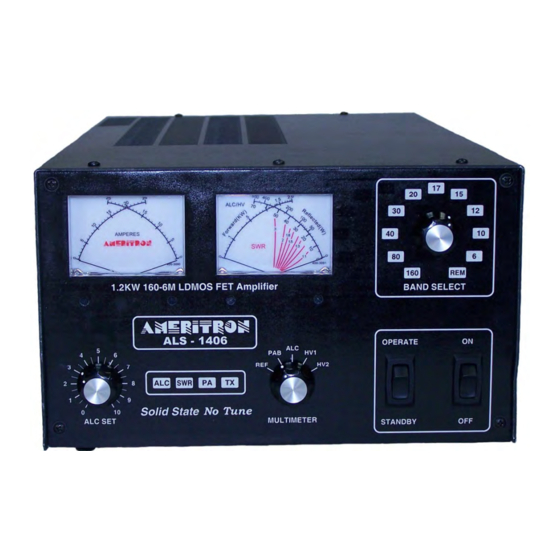
Page 15: Front Panel Controls
Front Panel Controls Figure 5 Amplifier Front Panel The front panel contains the following indicators and controls. To prevent damage, become familiar with the front panel before operating the amplifier. 1 PA Module Current meters 2 Forward Power meter and Multimeter (reflected power, module RF balance, ALC, and Module supply voltages) selected by knob 7. -
Page 16: Amplifier Rear Panel
50-ohm coaxial cable and system beyond must safely handle at least 1200 watts. RADIO INTERFACE This connector is for use with Ameritron radio interface cables. It allows automatic band selection (following the radio). It also provides amplifier actuation in transmit mode... -
Page 17: Interconnections
REMOTE These RJ45 connectors are for an Ameritron remote control head, or remote operation with an interface box. It provides access to controls, including most metering functions. Interconnections 1. If you use a desktop grounding bus system, connect the station ground bus to the amplifier’s rear panel wing nut. -
Page 18: Optional Radio Interface Cables
AMP ENABLE IN connector on the tuner, and run a cable from the AMP ENABLE OUT connector to the RELAY connector on the amp. Optional Radio Interface Cables ALS-1406/ALS-706/ALS-1306/RCS-12 Radio Interface Cables available from Ameritron. Model No. Description Notes... -
Page 19: Operation
(power amplifier) or filter damage may occur. Ameritron guarantees to exceed FCC Part 97.317 harmonic suppression standards inside the amateur bands listed in the table above. Ameritron does not guarantee harmonic suppression or operation outside amateur bands. Most commercial services prohibit use of non-commercial radio equipment. -
Page 20: Initial Operation
Initial Operation For your personal and equipment safety, double-check all wiring and connections (fig. 1) before turning power on. After you have verified amplifier connections, follow the procedures below. The following steps are necessary during initial checks: 1. Place the MULTIMETER switch (fig.5 ref 7) in the HV2 position. Place the ALC SET control (fig.5 ref 5) full clockwise (10 on knob scale). -
Page 21: Alc Adjustment
12. Briefly, increase exciter power until the amplifier reaches 1200 watts output, or the exciter reaches maximum power without exceeding 1200 watts amplifier power. 13. After you have verified all of this, the amplifier is ready to operate. With 100 watts PEP, this amplifier should show approximately 1200 watts of output power. -
Page 22: Warning Lights
Warning Lights The ALS-1406 has three primary warning lights in the center of the front panel. It also uses other standard LED’s as warnings, flashing them in a certain code that indicates problems. These lights serve the following functions: ALC: The yellow ALC light indicates ALC output. Flashing is normal when using ALC. A steady intense light indicates a problem. -
Page 23: Table 5 Rf Exposure Distance Chart
100W 600W 1200W Antenna Controlled Uncontrolled Controlled Uncontrolled Controlled Uncontrolled Frequency Gain Distance Distance in Distance Distance in Distance Distance in BAND in Meters Meters in Meters Meters in Meters Meters 160M 2.000 80/75M 4.000 7.000 10.2 10.2 14.4 10.4 10.150 10.4 14.8... -
Page 24: Table 6 Approximate Antenna Gain For Some Common Antennas
CFR Title 47 Part 97.13(C) (as of Apr. 1, 2020) requires the amateur operator to be in compliance with the radio frequency exposure requirements. The chart Table 5 above is a calculation of distances in meters for several different antenna gains using the formulae in the bulletin. -
Page 25: Als-1300Sps Interconnect Diagram
ALS-1300SPS Interconnect Diagram AC Mains Selection There are two different power supply modules that may be used in the ALS-1300/ALS- 1306/ALS-1406 power supply with different wiring to switch the power supply between 240 and 120 VAC. Identify which power supply module is used before trying to change the input voltages. -
Page 26: 50-Sps600-1B Power Supply Module
50-SPS600-1B Power Supply Module 220VAC 110VAC JUMPER Figure 8 50-SPS600-1B Line Voltage Jumpers For 220/240VAC operation (default setting), place the jumper on the 220VAC terminal. For 110/120VAC operation, place the jumper on the 110VAC terminal. Do not change any other jumpers on the board. Do this for both power supply modules in the power supply. -
Page 28: Als-1406 Limited Warranty
A detailed description of the problem, including details on the equipment. Deliver the product to the Ameritron or the nearest authorized service facility, or ship the same in its original container or equivalent, fully insured and with shipping charges prepaid.
Need help?
Do you have a question about the ALS-1406/S and is the answer not in the manual?
Questions and answers