Advertisement
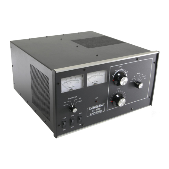
The Ameritron AL-1200 is a 1500 watt output linear amplifier
that operates from 160 through 15 meters. The Ameritron AL-
1200X is the export model and covers 160 through 10 meters.
The AL-1200 uses a single 3CX1200A7 tube in a class AB2
grounded grid circuit. CW, FM and RTTY efficiency is
improved by shifting the bias deeper into class B. The heavy
duty power supply and RF components, combined with a forced
air system utilizing chimneys, provide long service life for
expensive components. The AL-1200 is shipped factory wired
for 240 volt, 50/60 Hz power mains.
PLEASE READ THIS MANUAL BEFORE OPERATING THIS EQUIPMENT!
AMERITRON AL-1200
FULL POWER
LINEAR AMPLIFIER
INSTRUCTION MANUAL
116 Willow Rd.
Starkville, MS 39759
Advertisement
Table of Contents

Related Manuals for AMERITRON AL-1200


Summary of Contents for AMERITRON AL-1200
- Page 1 160 through 15 meters. The Ameritron AL- 1200X is the export model and covers 160 through 10 meters. The AL-1200 uses a single 3CX1200A7 tube in a class AB2 grounded grid circuit. CW, FM and RTTY efficiency is improved by shifting the bias deeper into class B.
-
Page 2: Unpacking Instructions
Inspect each item for visible damage. If any damage occurred during shipment, notify the transportation company immediately. 2. Save all packing materials in case you need to return your AL-1200(X) for factory service. The cartons have been designed to give maximum protection for this amplifier. - Page 3 FEATURES 1. Inexpensive tubes: the AL-1200 uses a single rugged 6. Two Illuminated Panel Meters: the AL-1200 has two il- 3CX1200A7 tube. luminated panel meters. . The Grid Current meter pro- vides a continuous reading of grid current and indicates proper operation of the amplifier.
-
Page 4: General Information
Normal amateur operation in CW and SSB will AMERITRON 116 not cause heat damage to components on any recommended tap. Willow Road It is always advisable to use the maximum speed (air flow) that Starkville, MS 39759 the level of noise permits to extend component life. -
Page 5: Transformer Installation
This is the fuse pack and chimney color coded insulating boots(see Fig. 1) for 240V operation. For for the AL-1200. Remove the top 7/16" nuts from the four 220V operation, see page 5. Caution: Do not use the 220V transformer mounting bolts inside of the amplifier. -
Page 6: Tube Installation
5. Tape up the BRN/WHT wire because it will not be used. Fig. 4 Fig. 3 Recent production model AL-1200 amplifiers have a neutralization tab located next to the 3CX-1200A7. This change results in additional efficiency on 21 and 28 MHz. - Page 7 FILAMENT/BLOWER WIRING INSTRUCTIONS The AL-1200 amplifier comes prewired for 240V line voltage and with the blower prewired for medium high fan speed. This page gives filament transformer connection details for various line voltages and blower speeds. The five lug terminal strip and the single lug terminal strip are located immediately behind the ON/OFF rocker switch inside the unit.
- Page 8 1. Connect the RF output of the exciter to the RF IN connector 100mA of current when pulled to ground. on the rear of the AL-1200 with 50 ohm coax. Use any good 4. Connect a short ground lead from a good earth and RF ground quality 50 ohm cable long enough to connect the amplifier to the exciter.
-
Page 9: Power Connections
POWER CONNECTIONS Do not operate the Amplifier in excessively warm locations The AL-1200 is supplied with a NEMA 6-15P plug for 240V or near heating vents or radiators. Be sure air can circulate AC operation. Operation with power main voltages below freely around and through the Amplifier cabinet. -
Page 10: Operation
SSB position. Plate current should now read 150 mA. Return the CW-SSB switch to the CW position. 1. Set the AL-1200 front panel switches as follows: POWER TO OFF Note: The no drive currents will vary up to 25% due to OPR-STBY TO component and line voltage tolerences. - Page 11 2000 RF Watts scale. The AL-1200 will operate with full output on all WARC bands except 24.5 MHz. The AL-1200X (export model) will operate with full output on all WARC bands.
-
Page 14: Parts List
PARTS LIST...
Need help?
Do you have a question about the AL-1200 and is the answer not in the manual?
Questions and answers